Stroke position control device of valve executing mechanism

A valve execution and control device technology, applied in the direction of valve devices, valve operation/release devices, valve details, etc., can solve the problems that the adjustment accuracy is difficult to meet the accuracy requirements, the control part has a large structure, and the installation space is large, so as to improve the control The effect of adjusting accuracy, eliminating transmission gap, and reducing installation space

Active Publication Date: 2011-04-13
YANGZHOU ELECTRIC POWER EQUIP MFG FACTORY CO LTD +2
View PDF0 Cites 4 Cited by
  • Summary
  • Abstract
  • Description
  • Claims
  • Application Information

AI Technical Summary

Problems solved by technology

[0002] At present, most of the travel position control mechanism and signal indication mechanism used on valve electric actuators are two independent components, which occupy a relatively large installation space, resulting in a large structure of the control part of the actuator, and the stroke position control mechanism and signal indication. The gear transmission group in the mechanism does not have an anti-backlash mechanism, especially for the adjustment control of the adjustable valve, the adjustment accuracy is difficult to meet the accuracy requirements specified in the standard

Method used


Image

  • Stroke position control device of valve executing mechanism
  • Stroke position control device of valve executing mechanism
  • Stroke position control device of valve executing mechanism

Examples


Embodiment Construction

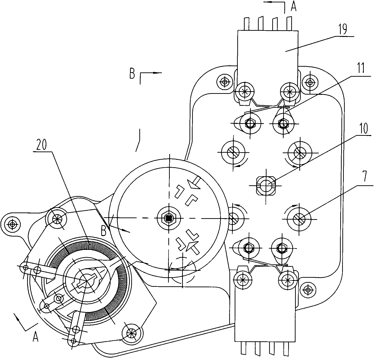
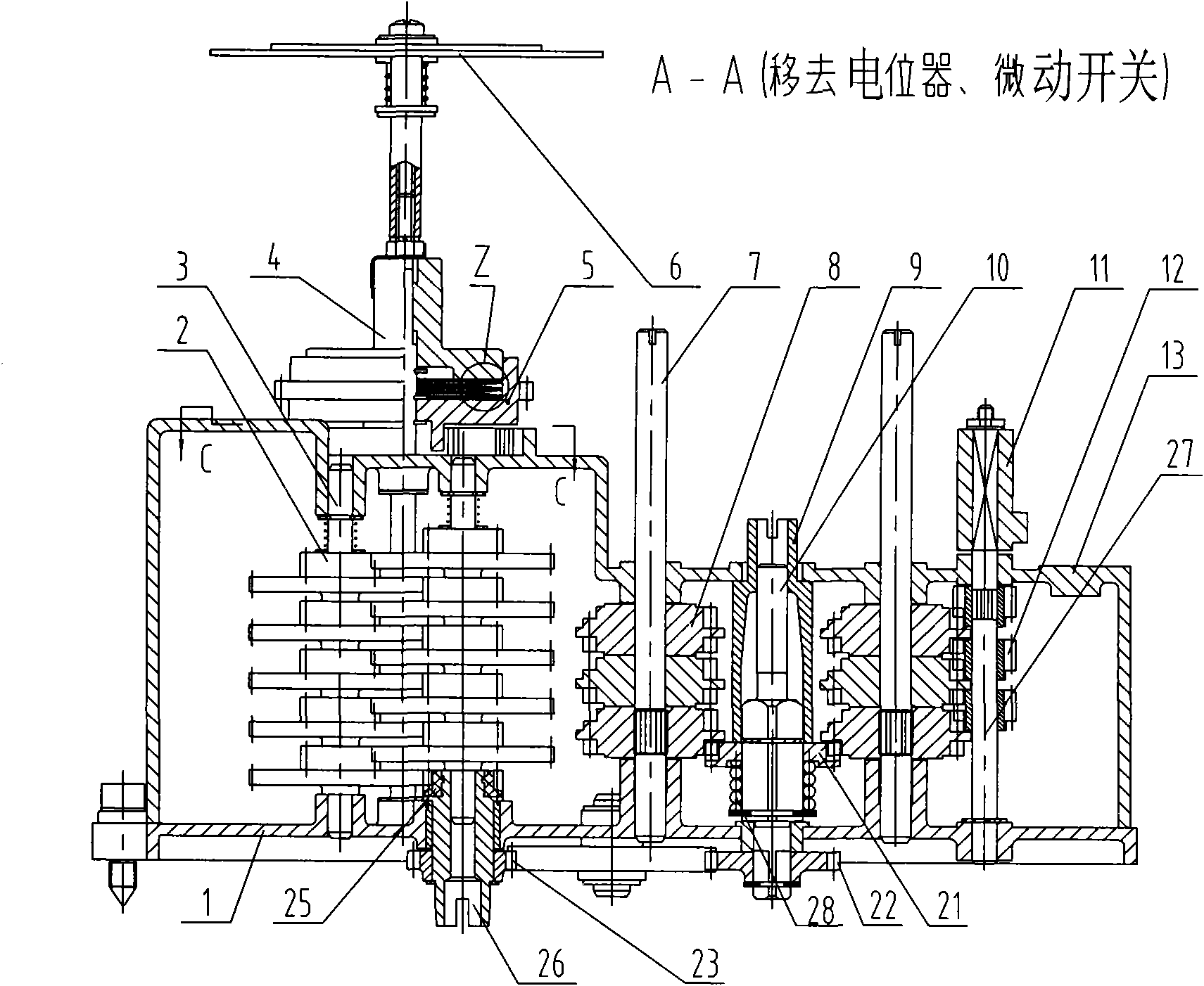
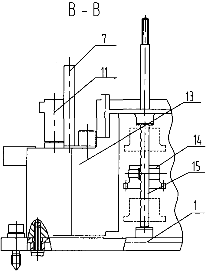
[0018] The present invention will now be described in further detail in conjunction with the accompanying drawings and preferred embodiments. These drawings are all simplified schematic diagrams, which only illustrate the basic structure of the present invention in a schematic manner, so they only show the configurations related to the present invention.

[0019] Such as Figure 1-4 As shown, a valve actuator stroke position control device includes a stroke input end 26, a casing 13, a bottom plate 1, a transmission shaft, a transmission gear set, and a micro switch 19, and the transmission gear set includes a coupling gear 21, The intermediate gear set 8 and the switch gear set 12, wherein the axial movement of the coupling gear 21 is sleeved on the coupling 10, the intermediate gear set 8 is sleeved on the adjustment shaft 7, and the micro switch gear set 12 is sleeved On the camshaft 27, the intermediate gear set 8 and the switch gear set 12 include ones, tens and hundreds...


PUM


Abstract

The invention relates to a stroke position control device of a valve executing mechanism, which comprises a stroke input end, a case, a base plate, a drive shaft, a drive gear set, a microswitch, a potentiometer, a scene opening indication mechanism, and the like. Motion is input by the stroke input end, passes through the drive gear set and the gear shaft and finally drives the microswitch, the potentiometer and the scene opening indication mechanism, therefore, the control and indication of opening and closing the valve are realized. The invention combines a stroke position control mechanism and a signal indicating mechanism and greatly reduces installation space, thereby shortening the structural size of the control part of the valve executing mechanism, eliminating the clearance of the gear drive set in the stroke position control mechanism and the signal indicating mechanism and further improving regulation and control precision.

Description

technical field [0001] The invention relates to a valve electric actuator component used in the field of process control, in particular to a stroke position control device of a valve actuator. Background technique [0002] At present, most of the travel position control mechanism and signal indication mechanism used on valve electric actuators are two independent components, which occupy a relatively large installation space, resulting in a large structure of the control part of the actuator, and the stroke position control mechanism and signal indication. The gear transmission group in the mechanism does not have an anti-backlash mechanism, especially for the adjustment control of the regulating valve, the adjustment accuracy is difficult to meet the accuracy requirements specified in the standard. Contents of the invention [0003] In order to overcome the above defects, the technical problem to be solved by the present invention is to propose a stroke position control d...

Claims


Application Information

Patent Timeline
Patent Type & Authority Applications(China)
IPC IPC(8): F16K31/02F16K37/00F16K31/53
Inventor 刘伟军余于仿朱乐尧樊高鹏张为
Owner YANGZHOU ELECTRIC POWER EQUIP MFG FACTORY CO LTD
Why Eureka
Try Eureka