High-power LED panel lamp for metro lighting

An LED panel light and high-power technology, which is applied to the parts of lighting devices, cooling/heating devices of lighting devices, lighting devices, etc., can solve the problems of difficult heat dissipation of high-power LED lamp beads, hidden safety hazards, and heavy lamps and lanterns. , to achieve the effect of high light output efficiency and reliability, convenient disassembly and maintenance, and uniform brightness

Active Publication Date: 2011-04-13
SOUTH CHINA UNIV OF TECH +1
View PDF4 Cites 7 Cited by
  • Summary
  • Abstract
  • Description
  • Claims
  • Application Information

AI Technical Summary

Problems solved by technology

Under the premise of meeting the energy-saving standards, although low-power LED panel lights can better solve the glare problem, it is difficult to meet the ground illumination requirements of the subway, and the low-power LED lamp beads have chip and packaging structure defects, resulting in low-power LED lamps. Large light attenuation
In the existing side-emitting high-power LED panel light, the high-power LED lamp beads are located on the side of the lamp, and the bright spots are obvious at the position of the lamp beads. If the frame is widened to eliminate the bright spots, the efficiency of the lamp will be low. To meet the illumination requirements, it is necessary to increase The number of high-power LED lamp beads, the heat dissipation problem of high-power LED lamp beads is difficult to solve, and the side-emitting high-power LED panel light needs to add a light guide plate, the weight of the entire lamp is relatively large, and there are potential safety hazards

Method used


Image

  • High-power LED panel lamp for metro lighting
  • High-power LED panel lamp for metro lighting
  • High-power LED panel lamp for metro lighting

Examples


Embodiment Construction

[0021] The specific implementation of the present invention will be further described below in conjunction with the accompanying drawings, but the implementation and protection scope of the present invention are not limited thereto.

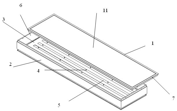
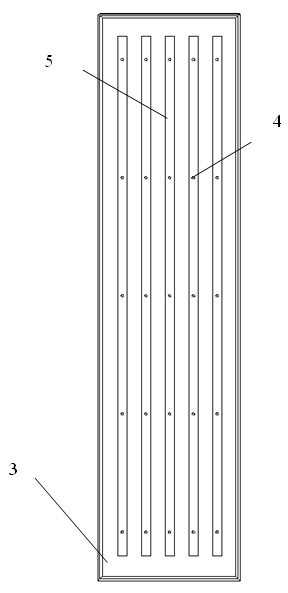
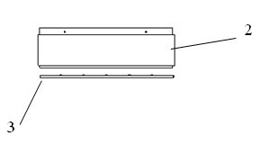
[0022] Such as Figure 1~3 , a high-power LED panel light for subway lighting, comprising a bottom aluminum plate 3, a lamp front cover 1, a lamp side frame 2 and a strip-shaped aluminum substrate 9, the bottom aluminum plate 3 and the lamp side frame 2 are connected to form a lamp with an opening The shell, the edge of the opening is connected with the edge of the front cover 1 of the lamp to form a space, and the aluminum plate 3 on the bottom surface is stamped with a number of grooves 5 for installing the long aluminum substrate, wherein the screw 4 is fixed in the middle of the groove 5, and the groove The long side of 5 is parallel to the long side of the bottom aluminum plate 3, several grooves 5 are equidistantly distributed along the sho...


PUM


Abstract

The invention discloses a high-power light-emitting diode (LED) panel lamp for metro lighting. The panel lamp comprises a bottom surface aluminum plate (3), a front lamp housing (1), a lateral lamp frame (2) and a strip-shaped aluminum substrate (9), wherein the bottom surface aluminum plate (3) is connected with the lateral lamp frame (2) to form a shell with an opening; the opening is connectedwith the front lamp housing (1) to form a space; a plurality of grooves (5) are punched on the bottom surface aluminum plate (3) for mounting the strip-shaped aluminum substrate; screws (4) are fixedin the middle of the grooves (5); the long sides of the grooves (5) are parallel to the long side of the bottom surface aluminum plate (3); the plurality of grooves (5) are distributed along the short side of the bottom surface aluminum plate (3) at equal interval; a plurality of high-power LED lamp beads (8) are arranged along the long side of the strip-shaped aluminum substrate at equal interval; and the high-power LED lamp beads on the strip-shaped aluminum substrate (9) are arranged in alignment with an array. In the high-power LED panel lamp, a light emitting surface has uniform brightness, and the lamp has high light emitting efficiency and reliability.

Description

technical field [0001] The invention relates to the field of LED lighting, in particular to a high-efficiency, high-reliability and easy-maintenance high-power LED panel light for subway lighting. Background technique [0002] Due to high light efficiency, long life, low working temperature, non-toxic and non-electromagnetic pollution, LED has the characteristics of green and environmental protection, and is recognized as the fourth-generation lighting source. Due to the small light-emitting area of ​​LEDs, large luminous flux, and concentrated light energy, the glare is severe when directly used for indoor lighting. Therefore, when LEDs are used in the field of indoor lighting, it is usually necessary to install diffusing materials on the surface of lamps to disperse the light energy of LEDs. [0003] With the rapid development of my country's urban rail construction, subway transportation can solve the problems of restricting urban development, traffic congestion and air p...

Claims


Application Information

Patent Timeline
IPC IPC(8): F21S4/00F21V19/00F21V7/00F21V5/00F21V29/00F21Y101/02F21K9/20F21V29/50F21Y105/12F21Y115/10
Inventor 王洪刘光武王海宏袁敏正李文球张小凡
Owner SOUTH CHINA UNIV OF TECH
Why Eureka
Try Eureka