Multiple coal type low-nitrogen direct flow pulverized coal combustion device and control method of nozzle thereof

A technology of pulverized coal combustion and multi-type coal, which is applied in the combustion method, combustion using multiple fuels, combustion using lump fuel and powder fuel, etc. Coking and other problems, to achieve the effect of convenient operation, simple structure and flexible control

Inactive Publication Date: 2011-04-13
WUHAN HUASHI ENERGY & ENVIRONMENTAL ENG CO LTD
View PDF9 Cites 25 Cited by
  • Summary
  • Abstract
  • Description
  • Claims
  • Application Information

AI Technical Summary

Problems solved by technology

[0003] At present, in the pulverized coal combustion device of the power station pulverized coal tangential combustion type, there are usually angular burner groups evenly distributed at the four corners or multiple corners of the furnace wall, and the arrangement of the primary air nozzle and the secondary air nozzle of each angular burner group They are all corresponding to the same, that is, two or more layers of primary air nozzles are set, and at least one layer of secondary air nozzles is arranged above and below the primary air nozzles. The primary air nozzles are used to spray the primary air with coal powder, and the secondary air The nozzles make the secondary air form CFS I or CFS II. The primary air nozzles in the angle burner group are driven by connecting rods to swing vertically in the same direction at the same time, and the secondary air nozzles are fixed at the beginning of the design. The deflection angle of the horizontal position makes it impossible to control the swing. The disadvantages of this design are: (1) The primary air nozzle can only swing in the same direction as a whole, and only one oxidation zone (that is, the main combustion zone) and one reduction zone (main combustion zone) can be formed in the burner. burnout zone), the unconverted nitrogen element in the reduction zone will inevitably be converted into nitrogen oxides after entering the oxidation zone and discharged from the tail of the boiler, resulting in too high emissions of nitrogen oxides after the furnace exit, which cannot be further reduced. In order to meet environmental protection requirements Flue gas denitrification is required, and the investment and operation costs of existing denitrification technologies (such as SCR and SNCR) are very expensive, and when operating in this way, the boiler q 4 There are also different degrees of increase, resulting in a corresponding decrease in the efficiency of the pulverized coal combustion device; (2) Since the secondary air nozzle in the main combustion zone is fixed and does not swing in the horizontal direction and cannot swing independently in the vertical direction, it can only be fixed to form CFS I or CFS II, but it is impossible to freely switch between the two, and it is also impossible to change the mixing timing and degree of mixing with the primary air jet by controlling the horizontal and / or vertical swing angle of the secondary air according to the actual coal type into the furnace
The existing burner design is aimed at the change of pulverized coal by selecting different air rates, wind speeds, burner area heat loads, tangential circle diameters, and selecting reasonable secondary air speeds to organize good combustion conditions in the furnace. However, when the type of coal that enters the furnace changes greatly, even if the relevant parameters are adjusted, it still cannot adapt, which will cause coking in the furnace and increase the loss of incomplete combustion (that is, q 4 High), low load and poor combustion stability and other problems will follow, resulting in the failure to achieve the best combustion state

Method used


Image

  • Multiple coal type low-nitrogen direct flow pulverized coal combustion device and control method of nozzle thereof
  • Multiple coal type low-nitrogen direct flow pulverized coal combustion device and control method of nozzle thereof
  • Multiple coal type low-nitrogen direct flow pulverized coal combustion device and control method of nozzle thereof

Examples


Embodiment Construction

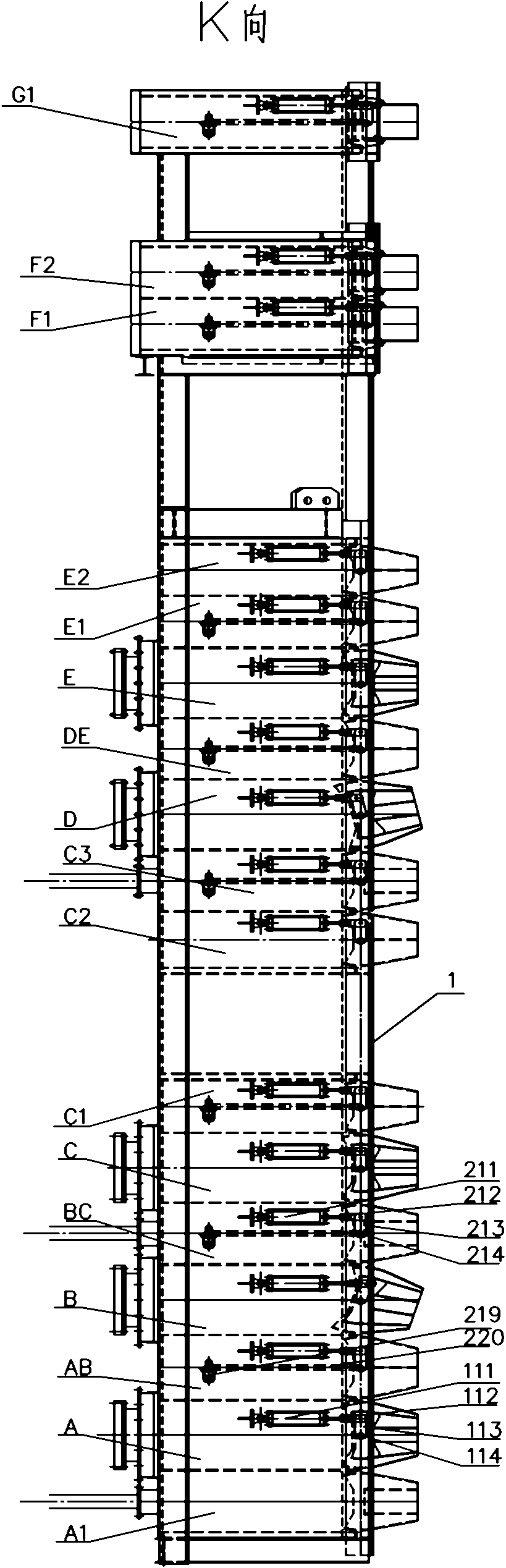
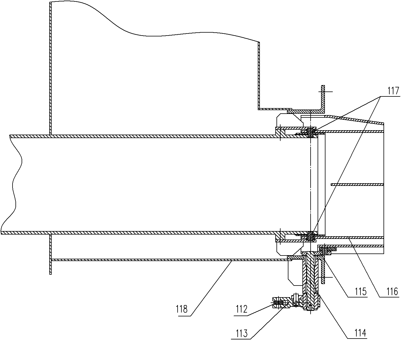
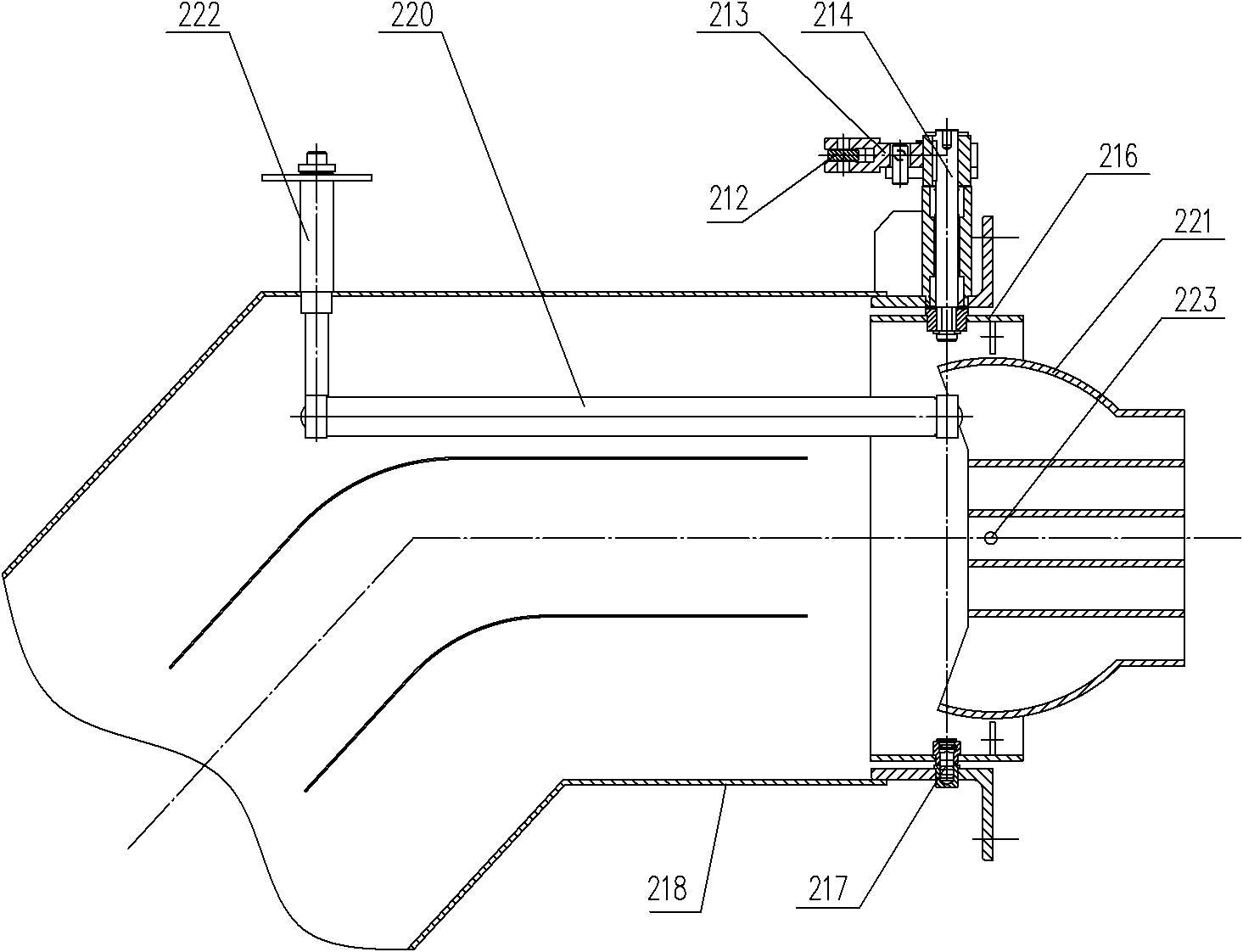
[0039] refer to figure 1 , Figure 4 and Figure 5 In this embodiment, the four corners of the multi-coal low-nitrogen direct-flow pulverized coal combustion device furnace water wall 1 are equipped with corner burner groups 2 (belonging to the pulverized coal combustion device of the four-corner tangential circle type), and the corner burners The device group 2 is composed of five layers of primary air nozzles installed on the furnace water wall 1 and the secondary air nozzles matched with them. The arrangement sequence from bottom to top is secondary air nozzle A1 for the installation of ignition equipment, primary air nozzle A, Secondary air nozzle AB, primary air nozzle B, secondary air nozzle BC, primary air nozzle C, secondary air nozzle C1, secondary air nozzle C2, secondary air nozzle C3, primary air nozzle D, secondary air nozzle DE , the primary air nozzle E, the secondary air nozzle E1, and the secondary air nozzle E2, among them, including the secondary air nozzl...


PUM


Abstract

The invention discloses a multiple coal type low-nitrogen direct flow pulverized coal combustion device and a control method of a nozzle thereof, which is used for solving the problems of the existing pulverized coal combustion device that the nozzle can not swing independently, the coal type adaptability is poor, the hearth is subject to coking and the emission load of nitric oxide is high. The technical scheme is as follows: the multiple coal type low-nitrogen direct flow pulverized coal combustion device comprises angular fuel nozzle groups arranged on four corners or multiple corners of the water wall of the hearth; the angular fuel nozzle groups comprise an upper fuel nozzle group and a lower fuel nozzle group, wherein each group comprises at least one layer of primary air nozzles, at least one layer of secondary air nozzles are distributed above and below the primary air nozzle, a gap of 1-6m is left between two fuel nozzle groups, and the primary air nozzle is the primary air nozzle capable of vertically swinging. Two main combustion zones and two burnout zones are realized by controlling independent swing of the primary air nozzle, pulverized coal dwell time in the furnace is prolonged, adaptability of the coal type is enlarged, the hearth is prevented from coking, and the purposes of obtaining lower NOX emission, lower load stable combustion, lower load protection parameter and lower q4 loss are obtained.

Description

technical field [0001] The invention relates to the coal-fired power generation industry, in particular to a multi-coal low-nitrogen direct-flow pulverized coal combustion device and a control method for a nozzle. Background technique [0002] my country has a vast territory, complex geographical distribution of coal types, and a wide range of ingredients, unlike coal types in developed countries in Europe and the United States. Most of the existing pulverized coal boilers in power stations in mainland my country are digested and absorbed by imported technologies. The burner of the boiler is only designed for a certain type of coal, such as lean coal, sub-bituminous coal, bituminous coal, lignite, etc., all need to be designed specifically for the burner, and the result of this design will lead to the change of the single-mode burner in the coal type. The expected combustion effect cannot be achieved, the adaptability of coal types is not wide, and the heating surface of the b...

Claims


Application Information

Patent Timeline
Patent Type & Authority Applications(China)
IPC IPC(8): F23C5/08F23C7/00
Inventor 邓学志冯旭明唐鹏程
Owner WUHAN HUASHI ENERGY & ENVIRONMENTAL ENG CO LTD
Why Eureka
Try Eureka