

Method for detecting base station feed system on line, base station system and antenna suite
A technology of an antenna feeder system and a base station system, which is applied to base station systems and antenna kits, and the field of online detection of base station antenna feeder systems, can solve the problems of low-performance base station systems, base station antenna feeder systems, many faults, and the inability of base station systems to perform accurate online detection. , to achieve the effect of improving the detection performance
- Summary
- Abstract
- Description
- Claims
- Application Information
AI Technical Summary
Problems solved by technology
Method used
Image

Examples
Embodiment Construction
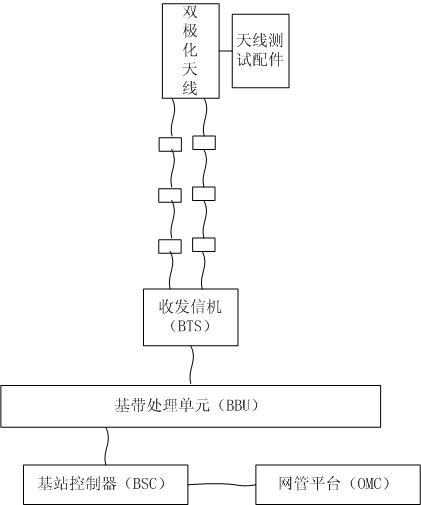
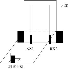
[0038] Such as figure 1 As shown, the base station system for online detection of the base station antenna feeder system includes the base station antenna system, the base transceiver station (BTS) and the base station antenna feeder system connected between them. The base station antenna system includes an antenna test accessory placed at a fixed position on the antenna for fixed testing of the mobile terminal; the antenna test accessory includes a fixed test position for placing the mobile terminal for testing, so that the test mobile terminal transmits signals when the test position is fixed The polarization direction of the base station and the polarization direction of each receiving antenna of the base station are relatively fixed, and the output characteristics of each receiving antenna of the base station are fixed within a preset error range.
[0039] The output characteristic of the receiving antenna of the base station is fixed within the preset error range, which m...
PUM
 Abstract
Description
Claims
Application Information