Method for positioning and detecting low-density concealed ore bodies in gallery gravity total spatial domain

A full-space, low-density technology that can be used in measurement devices, gravitational field measurement, geophysical measurement, etc.

Active Publication Date: 2014-11-26
KUNMING UNIV OF SCI & TECH
View PDF5 Cites 14 Cited by
  • Summary
  • Abstract
  • Description
  • Claims
  • Application Information

AI Technical Summary

Problems solved by technology

However, this paper only studies the density and structure of the underground gravity, and the terrain correction in the near area is corrected by the ground method, and no research on the location prediction of hidden ore bodies has been carried out; in 2012, Zhang Zheng was in Xinjiang. domain) to ...

Method used

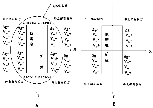
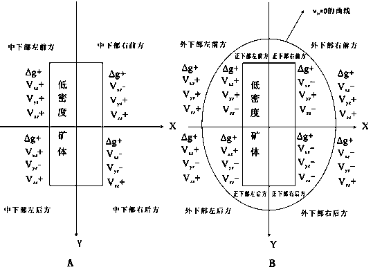
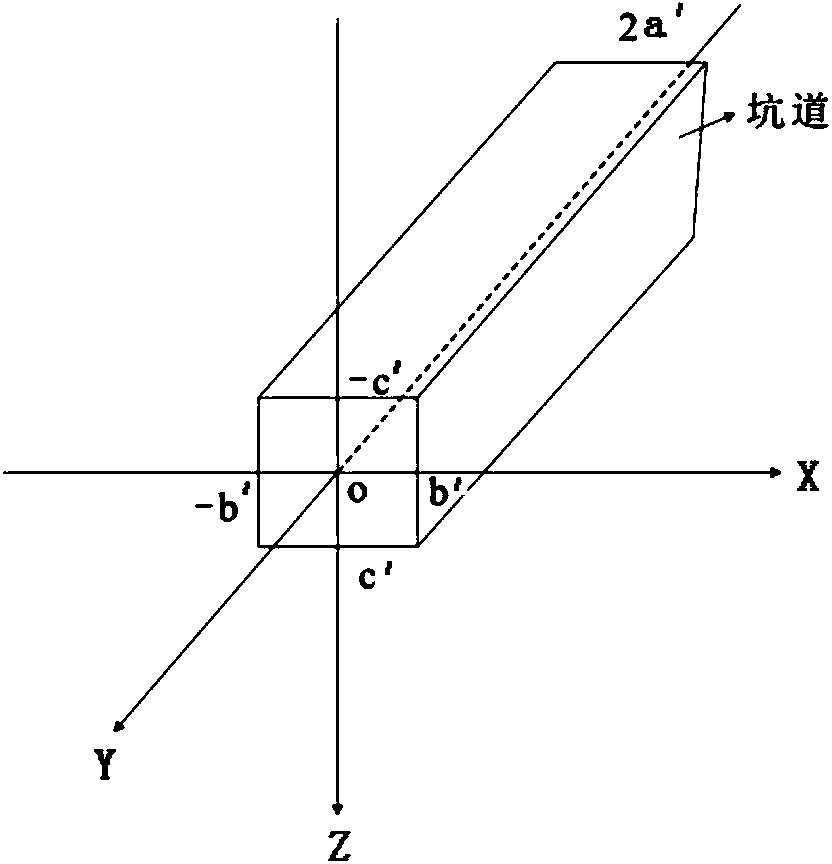

Image

  • Method for positioning and detecting low-density concealed ore bodies in gallery gravity total spatial domain
  • Method for positioning and detecting low-density concealed ore bodies in gallery gravity total spatial domain
  • Method for positioning and detecting low-density concealed ore bodies in gallery gravity total spatial domain

Examples


Embodiment 1

[0097]Example 1: The method of detecting low-density concealed ore bodies in the full space domain of tunnel gravity is applied in the deep ore prospecting of potash salt deposits in southeastern Yunnan, and the application effect is good. The specific content is as follows:

[0098] (1) Collect various rock and ore samples in the survey area, and conduct identification to determine the type of rock and ore

[0099] A total of 26 specimens were collected, including 11 surrounding rocks and 15 ores. The identification results were: 11 mudstones and 15 potassium salt ores.

[0100] (2) Measure the density of rocks and ores in the survey area, and count the average density of rocks and ores. When the average density of ores is significantly lower than that of surrounding rocks, the physical property prerequisite for applying this method is met;

[0101] The density of the rock ore specimens was obtained by dividing the mass by the volume. The mass of the rock ore specimens was me...

Embodiment 2

[0156] Example 2: The method of detecting low-density concealed ore bodies in the whole space domain of tunnel gravity is applied in a coal mine in southeast Yunnan, and the prospecting effect is good. The specific content is as follows:

[0157] (1) Collect various rock and ore samples in the survey area, and conduct identification to determine the type of rock and ore

[0158] A total of 20 specimens were collected, including 10 surrounding rocks and 10 ores. The identification results were: 10 sandy mudstones and 10 coal ores.

[0159] (2) Measure the density of rocks and ores in the survey area, compare the density characteristics of rocks and ores, and determine the physical property prerequisites for applying the method according to the density difference. When the average density of the ore is significantly lower than the density of the surrounding rock, the physical properties of the method are available premise;

[0160] The density of rock ore specimens is obtained ...


PUM

PropertyMeasurementUnit
Average densityaaaaaaaaaa

Abstract

The invention discloses a method for positioning and detecting low-density concealed ore bodies in a gallery gravity total spatial domain. The method includes the steps that firstly, field gallery gravity and gravity gradient observation is conducted, various corrections are conducted on observation data and include the earth tide correction, the null shift correction, the terrain correction, Bouguer correction, latitude correction, gallery correction, gob correction, backfilling zone correction and the like; secondly, concealed ore body positioning detection is conducted according to the gravity anomaly and the gravity gradient anomaly in the X direction, the Y direction and the Z direction, wherein the gravity anomaly and the gravity gradient anomaly are obtained after correction is conducted. The method solves the problems that metal ore bodies are difficult to position in the total spatial domain, and according to other object detection methods, the deep ore bodies are difficult to position and detect accurately due to the influences of electromagnetic interference and anomaly multiple solutions.

Description

technical field [0001] The invention relates to a method for positioning and detecting a low-density concealed ore body in a high-precision tunnel gravity full-space domain, and belongs to the field of mineral resource exploration. Background technique [0002] Low-density concealed orebodies refer to concealed orebodies whose ore density is significantly lower than that of ore-hosting surrounding rocks. The location detection of concealed ore deposits (bodies) is one of the main problems in the scientific frontier of metallogenic and metallogenic prediction and in the field of mineral exploration. Usually, geophysical prospecting methods (such as direct current method, magnetic method, electromagnetic method) are used in the half-space domain ( Such as the surface) to detect hidden ore bodies, but these geophysical methods are difficult to achieve success in the deep and full space domain hidden ore deposit (body) positioning detection due to their strong multi-solution and...

Claims


Application Information

Patent Timeline
IPC IPC(8): G01V7/00
Inventor 李文尧韩润生
Owner KUNMING UNIV OF SCI & TECH
Why Eureka
Try Eureka