

Daytime celestial body detecting device
A detection device and a star technology, which is applied in the field of daytime star detection devices, can solve problems such as difficult to improve the signal-to-noise ratio, and achieve the effects of high cost performance, suppression of stray light, and high image quality
- Summary
- Abstract
- Description
- Claims
- Application Information
AI Technical Summary
Problems solved by technology
Method used
Image

Examples
Embodiment Construction
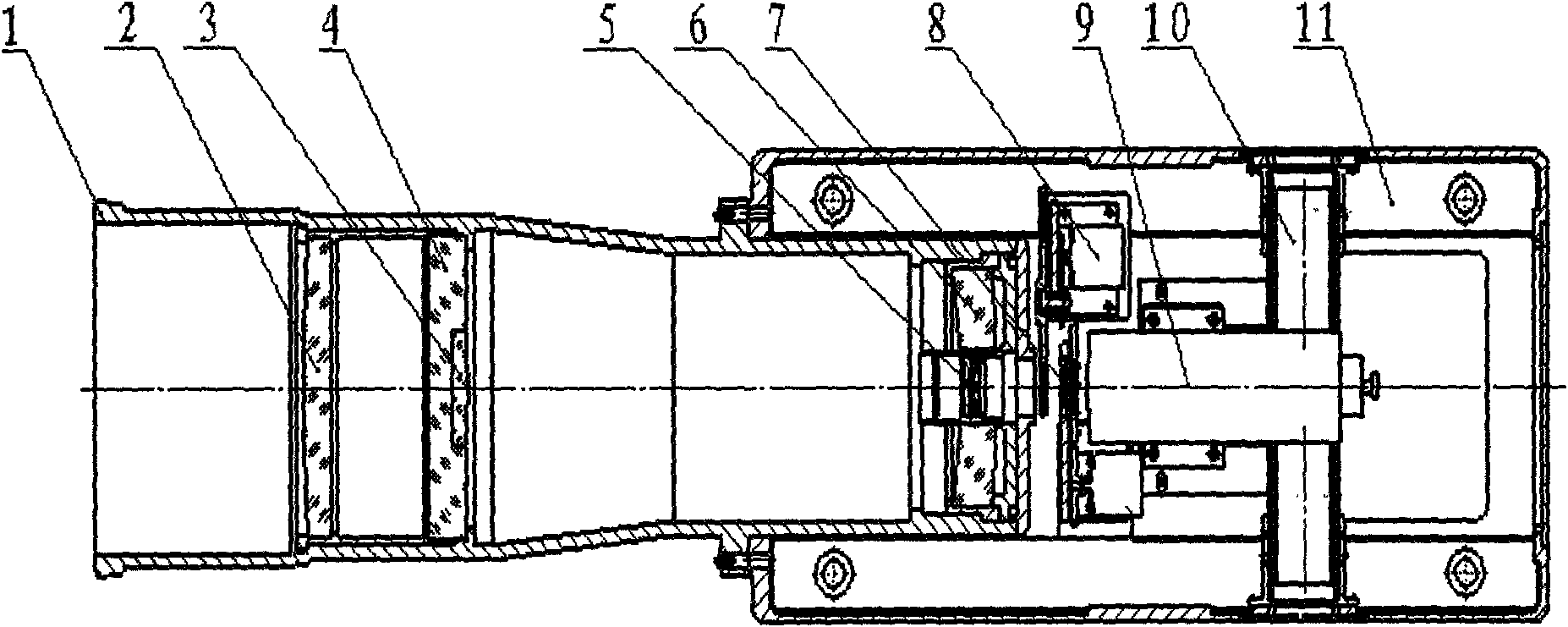
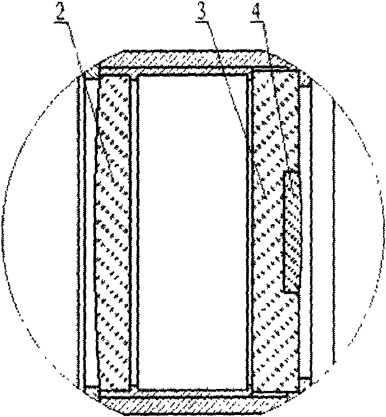
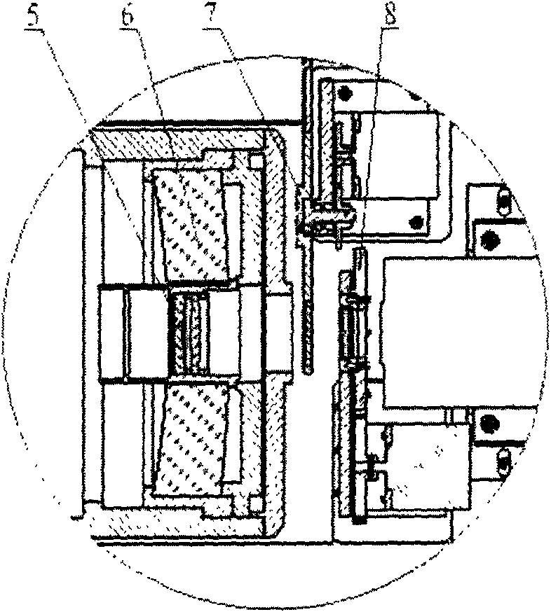
[0033] Such as figure 1 , 2 , 3, the present invention consists of shading cover 1, protective glass 2, plate glass 3, mirror 4, two-piece compensating mirror group 5, main mirror 6, optical filter turntable and adjustment mechanism 7, polarizer and its The adjustment mechanism 8, the CCD camera 9, the cooling channel 10, and the chassis 11 are composed. Among them, the protective glass 2, the flat glass 3, the reflection mirror 4, the two-piece compensating mirror group 5, and the main mirror 6 form a symmetrical fold-back optical system. The hood 1 and the symmetrical fold-back optical system are installed in the same lens barrel, and the lens barrel is installed on the chassis 11, and the chassis 11 is equipped with a filter and its adjustment mechanism 7, a polarizer and its adjustment mechanism 8, and a CCD camera 9 10 heat dissipation channels.
[0034] The hood 1 is installed at the front of the system. When measuring stars in the daytime, since the background is the...
PUM
| Property | Measurement | Unit |
|---|---|---|
| Field of view | aaaaa | aaaaa |
| Entrance pupil diameter | aaaaa | aaaaa |
Abstract
Description
Claims
Application Information