LED (Light-Emitting Diode) lamp driving circuit

A technology for driving circuits and LED lamps, which is applied to the layout of electric lamp circuits, electric light sources, lighting devices, etc., can solve the problems of increased power consumption of sampling resistors, increased costs, and uncontrollable power consumption of current sharing circuits, etc., to improve drive efficiency, The effect of simple circuit and low price

Active Publication Date: 2014-04-16
SHENZHEN HUNTKEY ELECTRIC
View PDF7 Cites 0 Cited by
  • Summary
  • Abstract
  • Description
  • Claims
  • Application Information

AI Technical Summary

Problems solved by technology

Moreover, each constant current source must complete the current sampling independently, the power consumption of the sampling resistor will increase, and designing multiple constant current sources will also increase the cost
If one constant current source and multiple current mirror circuits are used to form a multi-channel constant current sharing circuit, the design can be simplified, but the power consumption of the current sharing circuit cannot be controlled

Method used


Image

  • LED (Light-Emitting Diode) lamp driving circuit
  • LED (Light-Emitting Diode) lamp driving circuit
  • LED (Light-Emitting Diode) lamp driving circuit

Examples


Embodiment Construction

[0023] It should be understood that the specific embodiments described here are only used to explain the present invention, not to limit the present invention.

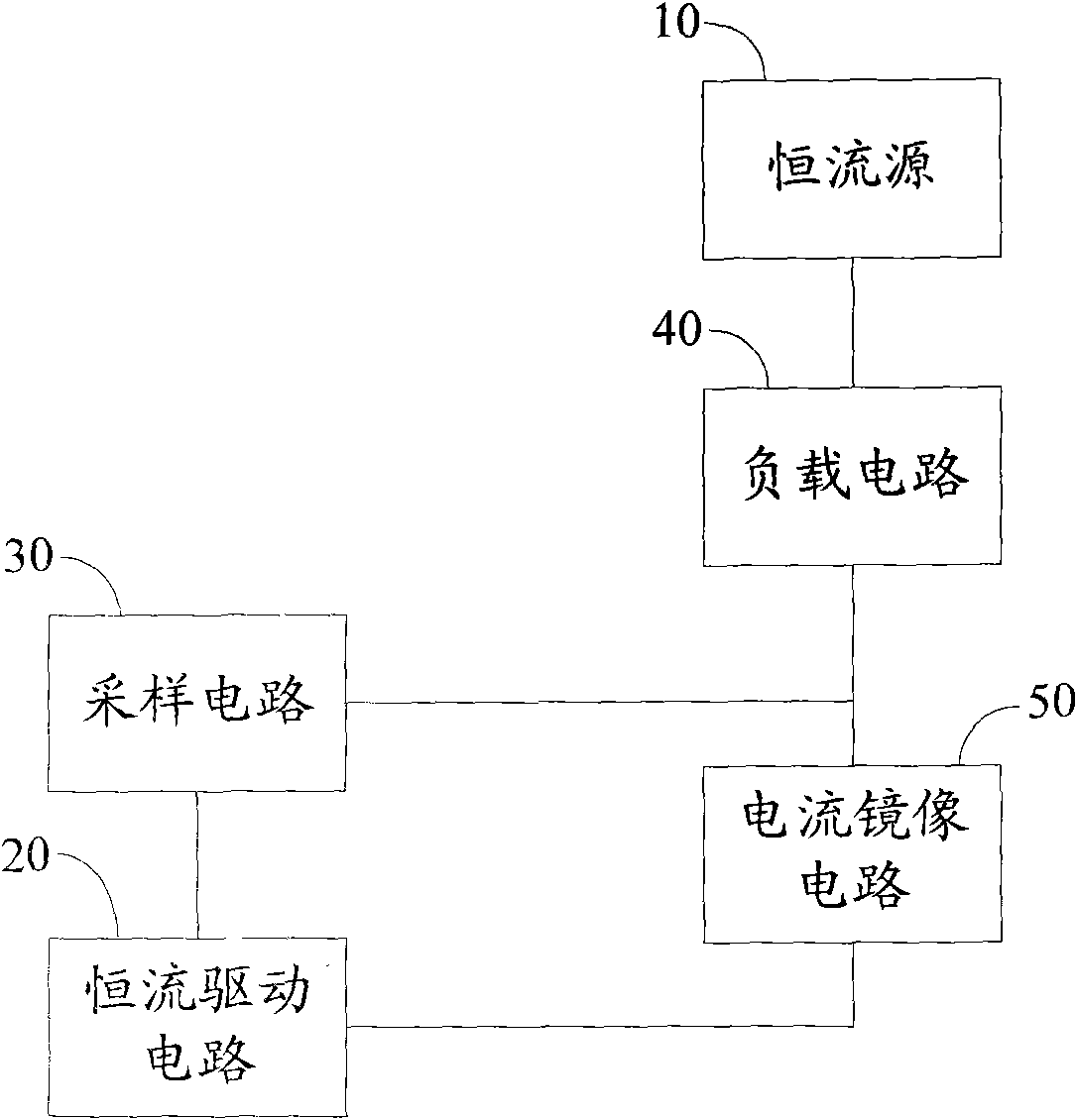
[0024] figure 1 It is a structural schematic diagram of an embodiment of the LED lamp driving circuit of the present invention.

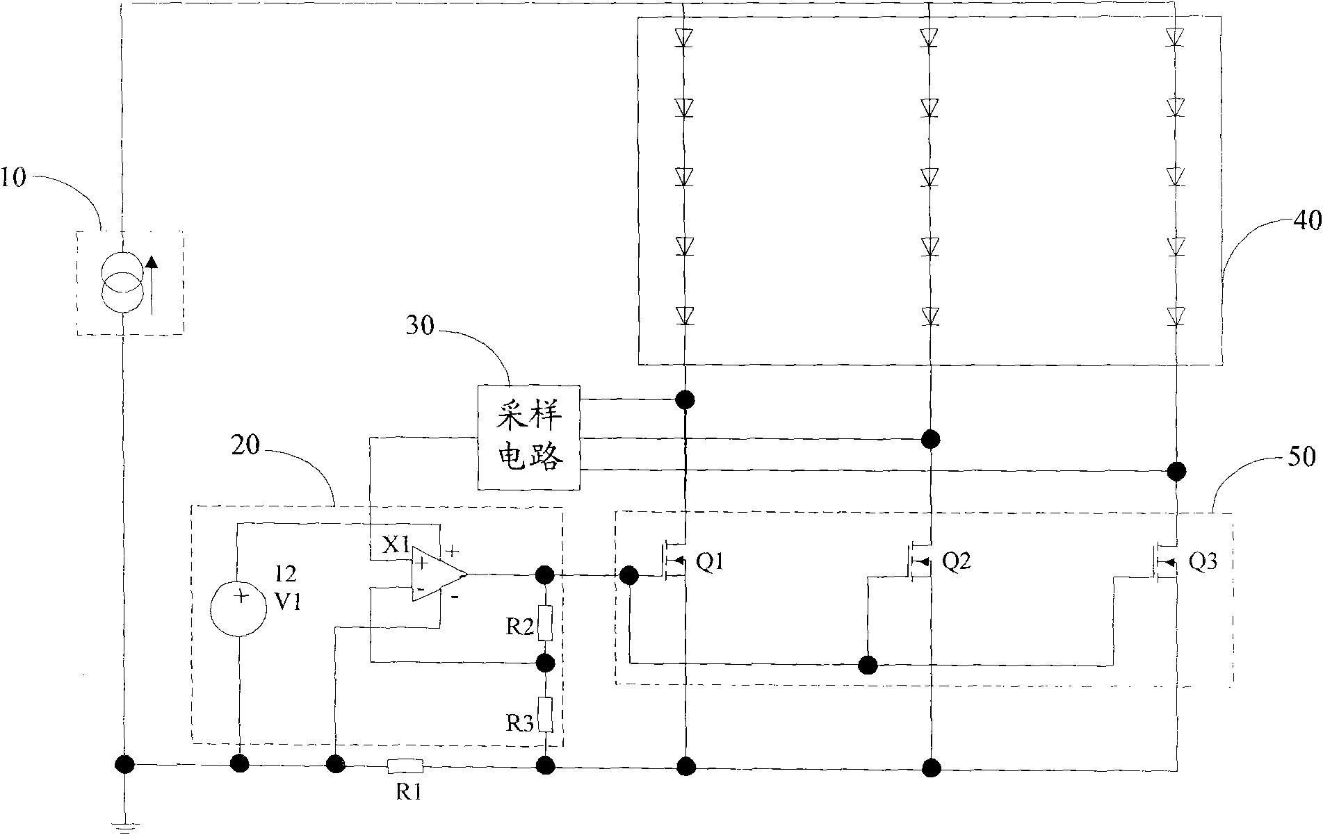
[0025] The LED lamp driving circuit of this embodiment adopts a constant current source and multiple current mirror circuits to form a multi-channel constant current equalizing circuit, including a constant current source 10, a constant current drive circuit 20, a sampling circuit 30, at least one load circuit 40 and a load circuit. Circuit 40 corresponds to a current mirror circuit 50 connected thereto. Wherein, the multi-channel load circuit 40 is connected in parallel with the constant current source 10 . The sampling circuit 30 is used to collect the voltage of the logical combination of the current mirror circuit 50 . The constant current drive circuit 20 is connected to one of the ...


PUM


Abstract

The invention relates to an LED (Light-Emitting Diode) lamp driving circuit in which a constant-current source and multiple paths of current mirror circuits are used to form a multi-path constant-current current-sharing circuit. The LED lamp driving circuit comprises a constant-current source, a constant-current driving circuit, a sampling circuit, at least one load circuit and current mirror circuits correspondingly connected with the load circuits, wherein the load circuits are connected in parallel with a power supply, the sampling circuit is used for collecting the logic combination voltage of the current mirror circuits, and the constant-current driving circuit is connected with the sampling circuit and the current mirror circuits and controls the current-sharing adjustment of the current mirror circuits according to the voltage collected by the sampling circuit. The LED lamp driving circuit of the invention controls the current mirror circuits to perform current-sharing adjustment by collecting the logic combination voltage of the current mirror circuits, thereby not only meeting the high current-sharing accuracy, but also improving the driving efficiency; in addition, the LED (Light-Emitting Diode) lamp driving circuit has the advantage of simple circuit and low cost.

Description

technical field [0001] The invention relates to the technical field of driving circuits, in particular to an LED lamp driving circuit. Background technique [0002] With the intensification of the world's energy crisis, it has become a consensus to reduce energy consumption and protect the environment. LED lighting will replace energy inefficient first and second generation lighting technologies. For LED lighting, companies such as TI, ONSEMI, and PI have developed many products. The circuit topology includes BUCK, BOOST, FLYBACK, LLC and linear steady current, etc. The technologies used include the following two types: [0003] (1) Current-type PWM control technology, by directly sampling the current of the LEDs in series, comparing the sampling current with the reference voltage, and adjusting the duty cycle according to the comparison result, so as to control the working current of the LEDs. [0004] (2) Linear current stabilization technology, by directly sampling the...

Claims


Application Information

Patent Timeline
Patent Type & Authority Patents(China)
IPC IPC(8): H05B37/02
Inventor 段卫垠熊林生汪本强
Owner SHENZHEN HUNTKEY ELECTRIC
Why Eureka
Try Eureka