
Heat treatment method for rolling bearing device for wheel and cooling device for inner shaft

A heat treatment method and rolling bearing technology, applied in heat treatment furnaces, bearing components, heat treatment equipment, etc., can solve the problems of irregular discoloration of the outer peripheral surface, achieve uniform thickness and diffusion, suppress hardening irregularities, and omit the effect of turning steps

Active Publication Date: 2013-03-20
JTEKT CORP
View PDF1 Cites 0 Cited by
  • Summary
  • Abstract
  • Description
  • Claims
  • Application Information

AI Technical Summary

Problems solved by technology

In particular, in the outer ring 2, the hardened layer may reach the outer peripheral surface of the tube, and in some cases, the outer peripheral surface may be irregularly discolored

Method used


Image

  • Heat treatment method for rolling bearing device for wheel and cooling device for inner shaft
  • Heat treatment method for rolling bearing device for wheel and cooling device for inner shaft
  • Heat treatment method for rolling bearing device for wheel and cooling device for inner shaft

Examples


Embodiment Construction

[0038] With reference to the drawings, embodiments of the present invention will be specifically described below.

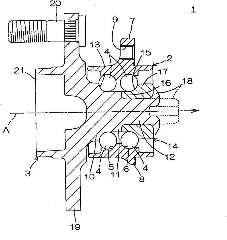
[0039] As mentioned above, figure 1 It is a cross-sectional view showing an example of the rolling bearing device 1 for a wheel. reference figure 1 , The rolling bearing device 1 for a wheel includes an outer ring 2, an inner shaft 3, and a plurality of rolling elements 4. The outer ring 2 has a tube shape, and the inner shaft 3 is inserted into the tube and shared with the outer ring 2 around the axis A Arranged axially, the rolling elements 4 are placed between the outer ring 2 and the inner shaft 3.

[0040] Double rows (two rows in the figure) track surfaces 5 and 6 for supporting the rolling elements 4 for rolling are formed on the inner circumference of the tube of the outer ring 2. Also, on the outer circumference of the tube, the flange 8 is formed integrally with the tube to protrude outward in the radial direction of the tube from a plurality of positions (...


PUM


Abstract

In the heat treating method, a raceway surface of an outer ring is subjected to heat treatment, while an entirety of an outer peripheral face of the outer ring is cooled by injecting water. Moreover, a raceway surface of an inner shaft is subjected to heat treatment, while a flange of the inner shaft is cooled by bringing it into contact with water. The cooling unit has a holding part for holding the flange while the flange is in contact with water.

Description

Technical field [0001] The present invention relates to a heat treatment method of a rail surface of a rolling bearing device for a wheel and a cooling unit for an inner shaft used in the heat treatment method. The rolling bearing device for a wheel is used to rotatably hold on a suspension device of an automobile or the like wheel. Background technique [0002] figure 1 It is a cross-sectional view showing an example of a rolling bearing device 1 for a wheel that has been widely used in recent years. reference figure 1 In this example, the rolling bearing device 1 for a wheel includes an outer ring 2 having the shape of a tube; an inner shaft 3 in which the inner shaft 3 is inserted into the tube and arranged coaxially with the outer ring 2; and The rolling elements 4 are arranged between the outer ring 2 and the inner shaft 3. [0003] Double rows (two rows in the figure) track surfaces 5 and 6 for holding the rolling elements 4 for rolling are formed on the inner circumference...

Claims


Application Information

Patent Timeline
Patent Type & Authority Patents(China)
IPC IPC(8): C21D9/40C21D1/10C21D1/62F16C33/64
CPCC21D1/63F16C33/64C21D2211/008F16C2326/02C21D9/40C21D1/62
Inventor 中村久信立龟正平稻田充宏长绳邦宏小栗正彦南义之白川直人
Owner JTEKT CORP
Features
  • Generate Ideas
  • Intellectual Property
  • Life Sciences
  • Materials
  • Tech Scout
  • Unparalleled Data Quality
  • Higher Quality Content
  • 60% Fewer Hallucinations
Learn More