Hinge for a window or a door

A hinge and bearing pin technology, applied in the field of hinges, can solve the problems of complex introduction of hinge pins and narrow site conditions, and achieve the effects of simplified operation, simplified manufacturing, and simple manufacturing.

Active Publication Date: 2011-04-13
SIEGENIA FRANK
View PDF5 Cites 4 Cited by
  • Summary
  • Abstract
  • Description
  • Claims
  • Application Information

AI Technical Summary

Problems solved by technology

In addition, with such a configuration, the introduction of the hinge pin into the bearing seat is complicated, in particular due to the tight space in the area of ​​the hinges of windows and doors

Method used


Image

  • Hinge for a window or a door
  • Hinge for a window or a door
  • Hinge for a window or a door

Examples


Embodiment Construction

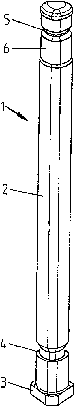
[0026] according to figure 1 As shown, a bearing pin 1 for a hinge for a window or door is designed as a long pin with a head 3 thickened relative to a shaft 2 . The shank 2 has grooves 4 , 5 and a taper 6 at the end, the groove 5 being in the region of the taper 6 .

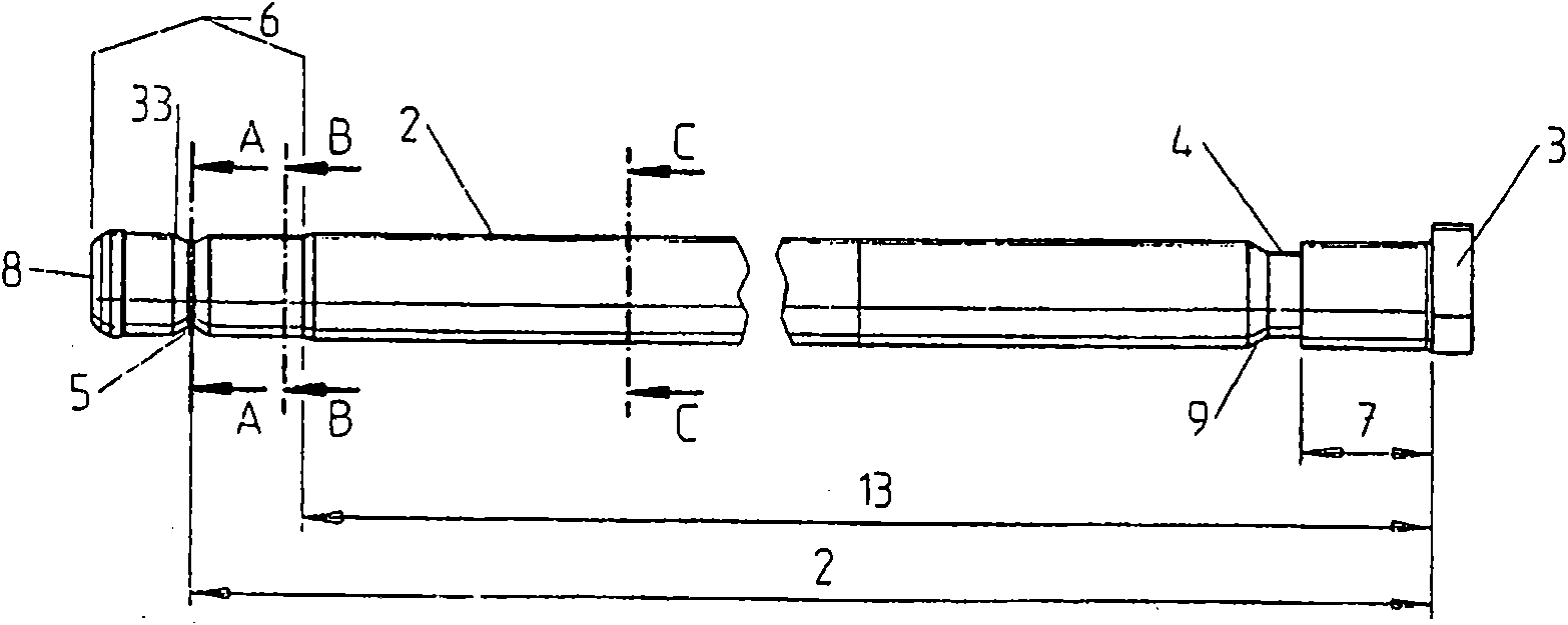
[0027] to combine figure 2 It can be seen that the groove 4 is widened relative to the groove 5 and has, in the groove wall at a distance 7 from the head 3 , a run at right angles to the shaft 2 , while the groove wall 9 inclined in the direction of the end 8 has a A gentler angle. The groove 5 is formed almost as a groove by two groove walls 10 , 11 running at gentle angles. The distance 12 from the groove 5 to the head 3 is indicated, while the taper 6 starts at a distance 13 .

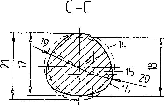
[0028] with the help of image 3 , 4 combined with 5 figure 2 It can be seen that the bearing pin has a kind of image 3 Different cross-sectional shapes 15 of the circle 14 indicated by dashed lines.

[0029] The shank 2 h...


PUM


Abstract

The invention relates to a hinge for a window or a door in which a bearing block (22) is attached to the frame and a hinge sleeve (36) is attached to the wing, wherein the bearing block (22) and the hinge sleeve (36) are swivelably connected together by way of a bearing pin (1), wherein the bearing pin (1) is held rotationally fixed in at least one bearing boss (23, 24) of the bearing block (22),wherein the bearing pin (1) has a cross sectional shape that deviates from a circular shape and wherein a sleeve (37) made of elastic material can be placed in the hinge sleeve (36) in rotationally fixed fashion. In order to simplify the manufacture of a non-cylindrical bearing pin that can be attached rotationally-fixed relative to the bearing block, it is provided that the bearing pin (1) has apolygonal multi-edged cross section at least in the area of the length section associated with the hinge sleeve (36) and the bearing block (22).

Description

technical field [0001] The invention relates to a hinge for a window or door according to the preamble of claim 1 . Background technique [0002] Hinges of this type are known from DE 29605809U1 and DE 202006008400U1. In the hinge known from DE 29 605 809 U1, the hinge pin has a cylindrical cross section with a flattened section and protrudes through the two bearing bores of the frame-side bearing seat. The bearing bore of the bearing seat has an opening corresponding to the flattening in the cross-section of the bearing pin, so that the bearing pin is accommodated in the bearing bore in a non-rotatable manner. Between the two bearing bores, the bearing pin projects through an essentially cylindrical joint sleeve formed from a plate, which is provided on the inside with a plastic bushing which is fixed relative to the joint sleeve. The plastic bushing is also adapted in cross-section to the flattening of the hinge pin. During the pivoting movement of the hinge sleeve and ...

Claims


Application Information

Patent Timeline
IPC IPC(8): E05D11/00E05D11/08E05D5/12
CPCE05D11/082E05Y2900/148E05Y2900/132E05D11/0018E05D5/128
Inventor B·克尔施A·蒂尔克
Owner SIEGENIA FRANK
Why Eureka
Try Eureka