Coffee machine

A coffee machine and coffee technology, which is applied to kitchen utensils, home utensils, beverage preparation devices, etc., can solve the problems of complicated operation process, large heat loss and high production cost, and achieve flexible operation, low production cost and simple and reasonable structure. Effect

Active Publication Date: 2011-04-20
GUANGDONG XINBAO ELECTRICAL APPLIANCES HLDG CO LTD
View PDF4 Cites 21 Cited by
  • Summary
  • Abstract
  • Description
  • Claims
  • Application Information

AI Technical Summary

Problems solved by technology

This kind of coffee machine has a large volume and high production cost. At the same time, the heat loss is large and the pressure is

Method used


Image

  • Coffee machine
  • Coffee machine
  • Coffee machine

Examples


no. 2 example

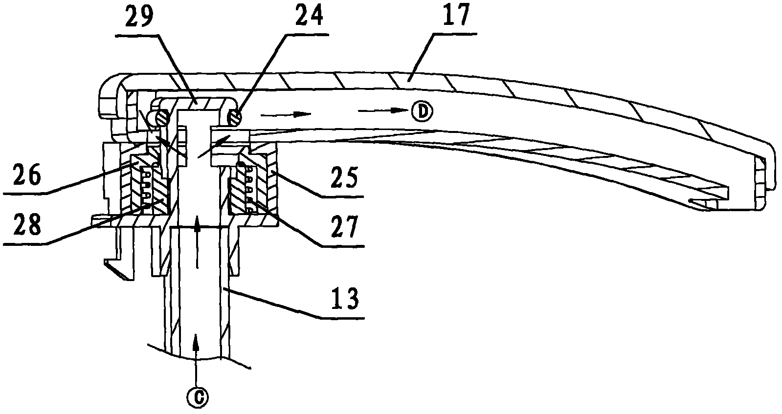
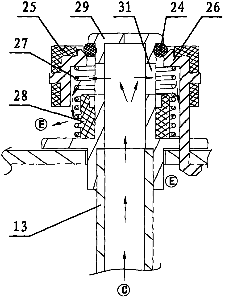
[0036] see Figure 7, the rear side of the top cover 5' is hinged on the top of the fuselage through the top cover shaft 37, and the inner bottom surface of the top cover is provided with an inner cover 19' corresponding to the top of the funnel; the bottom surface of the inner cover is provided with a water seepage hole, and a brewing nozzle 17' is fixed inside The water outlet pipe assembly includes a 7-shaped rotary joint 29', the lower end of which communicates with the pipeline of the heating element through the water outlet pipe 13, and the upper end is provided with a water outlet hole 31' which is rotationally connected and communicated with one end of the brewing nozzle. The other end of the mouth is provided with an opening corresponding to the inner cover. Other unmentioned parts are the same as the first embodiment.

[0037] Its working principle is: when the top cover 5' is flipped open, the brewing nozzle 17' rotates upward around the rotary joint 29' and covers...

no. 3 example

[0039] see Figure 8 and Figure 9 , The coffee storage cavity 40 is connected with the water tank 42 as a whole; the top of the water tank is integrally provided with a water tank cover 41, and the bottom is open and sealed with the bottom plate 43; the front side of the water tank cover 41 is closed to form a water retaining part, and the rear side is provided with a water injection hole. Other unmentioned parts are the same as the first or second embodiment.

no. 4 example

[0041] see Figure 10 and Figure 11 , the coffee storage cavity 38 and the water tank 2 constitute the upper body 1 of the fuselage, the upper body bottom is provided with the lower body 3, the lower body side is provided with a power switch 12, and the bottom surface is provided with a bottom cover 4'. The difference between the bottom cover 4' and the bottom cover in the first embodiment is that the center of the bottom is not provided with a power insertion port that is matched with the power connector. Other unmentioned parts are the same as the first or second embodiment.


PUM


Abstract

The invention relates to a coffee machine, comprising a machine body, a water tank, a funnel, a top cover and a heating element, wherein the front side and the rear side in the machine body are respectively fixedly provided with a coffee storage cavity and the water tank, and the top of the coffee storage cavity is open and can be covered by the top cover; the funnel is arranged at the place where the top of the storage cavity is open, and a brewing water nozzle is arranged above the funnel or at one side of the funnel; and the brewing water nozzle is communicated with the water tank by virtue of a water outlet pipe assembly and the heating element. In the invention, coffee and cold water are respectively stored in the coffee storage cavity and the water tank, thus realizing brewing and storage of coffee; brewed coffee can be conveniently poured out by combining the machine body provided with an independent handle and a split type base provided with a power supply connector; a seal ring is arranged between the end face of the funnel and an inner cover plate, so as to prevent coffee grounds from being poured out by mistake and steam from refluxing into the water tank, and meanwhilepressure in the funnel can be increased, the brewed coffee is more concentrated and fragrant, and the temperature of the coffee is higher; and due to the design of the movable top cover, hot water can be communicated with the brewing water nozzle when the top cover is closed.

Description

technical field [0001] The present invention relates to a coffee machine. Background technique [0002] In traditional coffee pots, the heating tube is basically arranged under the water tank, and the heating tube and the water tank are connected by a silicone tube, and a one-way valve is installed in the silicone tube. When the water in the water tank flows into the heat pipe, the volume of the water expands due to the rise of the water temperature, so that the water rushes up into the funnel above the body of the coffee pot. The brewed coffee is generally stored in a glass or stainless steel cup below the funnel, and the coffee is poured out of the glass or stainless steel cup when tasting. This kind of coffee machine has a large volume, high production cost, large heat loss and low pressure, so that the coffee temperature and extraction concentration are low, and the operation process is also relatively complicated. Contents of the invention [0003] The purpose of th...

Claims


Application Information

Patent Timeline
IPC IPC(8): A47J31/44A47J31/46
Inventor 郭建刚程玉军
Owner GUANGDONG XINBAO ELECTRICAL APPLIANCES HLDG CO LTD
Why Eureka
Try Eureka