Tailstock locking device

A locking device and tailstock technology, used in printing, rotary printing presses, printing plate preparation, etc., can solve problems such as poor locking effect, inability to lock firmly, and tailstock slippage.

Inactive Publication Date: 2011-04-20
杭州东城图像技术有限公司
View PDF4 Cites 4 Cited by
  • Summary
  • Abstract
  • Description
  • Claims
  • Application Information

AI Technical Summary

Problems solved by technology

[0003] The tailstock locking mechanism of the existing rotary net making machine uses two splints and a wrench to directly lock the tailstock on the slide rail. In order to protect the slide rail, nylon blocks are usually lined between the splint and the slide rail. The structure makes the locking effect very poor, and the tailstock will slip under the action of the axial force generated by the compressed air, and there is a defect that it cannot be locked firmly

Method used


Image

  • Tailstock locking device
  • Tailstock locking device

Examples


Embodiment Construction

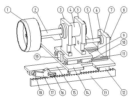
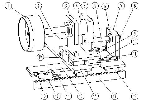
[0021] The technical solution of the present invention will be further specifically described below through examples and in conjunction with the accompanying drawings.

[0022] Such as figure 1 In the tailstock locking device shown, a bracket 3 is fixed on the small carriage 9, a bearing seat 4 is installed in the bracket 3, a plug 1 is fixed on one end of the rotating shaft 2, and the other end of the rotating shaft 2 is installed on the bearing seat 4 In the bearing, the rotating shaft 2 can rotate around its own axis line, the small carriage 9 is fixed on the large slider 10 of the guide rail 11 on the large carriage 14, the small carriage 9 can move along the guide rail 11, and the direction of its movement Parallel to the moving direction of the large carriage 14, the large carriage is fixed on the slide plate 12 of the main rail and can move along the main rail, which is fixed on the frame. An adapter plate 15 is fixed on the large carriage 14, and a pawl shaft 18 is fi...


PUM


Abstract

The invention relates to a tailstock locking device, comprising an end cap and a stand, wherein the stand is provided with a big carriage which moves and is positioned along the stand; the big carriage is provided with a small carriage which moves in parallel to the moving direction of the big carriage; the small carriage is provided with a support 1 which is horizontally provided with a rotation shaft in the direction consistent to the moving direction of the big carriage and the small carriage, and the end cap is arranged on one end of the rotation shaft; and a control device for controlling the movement amount of the small carriage is arranged between the big carriage and the small carriage. The tailstock locking device is suitable for circular screens with different lengths and ensures that slippage cannot generate under the action of the axial force of compressed air, therefore, the compressed air in the circular screen cannot be leaked.

Description

technical field [0001] The invention relates to a rotary screen machine used in the printing industry, in particular to a tailstock locking device of the rotary screen machine. Background technique [0002] The rotary screen making machine is a kind of equipment used to make printing templates. The rotary screen is a circular thin-walled long cylindrical object made of metal. When processing images on the rotary screen, in order to maintain its rigidity and roundness, plugs are usually installed at both ends of the rotary screen and the inside of the rotary screen is filled with compressed air. One of the two plugs is usually fixed on the drive shaft, and the position of the other plug can be adjusted arbitrarily along the guide rail on the frame to adapt to different lengths of the rotary screen. In order to realize this adjustment function, the plug needs to be installed on a tailstock, which can move along the guide rail. As long as the tailstock is locked, the position...

Claims


Application Information

Patent Timeline
Patent Type & Authority Applications(China)
IPC IPC(8): B41C1/14B41F15/38
Inventor 张杏华
Owner 杭州东城图像技术有限公司
Why Eureka
Try Eureka