
Frictional false twisting device

A device, false twisting technology, applied in the direction of rotational vibration suppression, textile and paper making, etc., to achieve the effect of easy adjustment

Inactive Publication Date: 2011-04-20
德特勒夫·格根斯
View PDF3 Cites 14 Cited by
  • Summary
  • Abstract
  • Description
  • Claims
  • Application Information

AI Technical Summary

Problems solved by technology

[0005] To date, no friction device is known in which the interaxial distance of the friction spindles can be adjusted steplessly on smaller scales

Method used


Image

  • Frictional false twisting device
  • Frictional false twisting device
  • Frictional false twisting device

Examples


Embodiment Construction

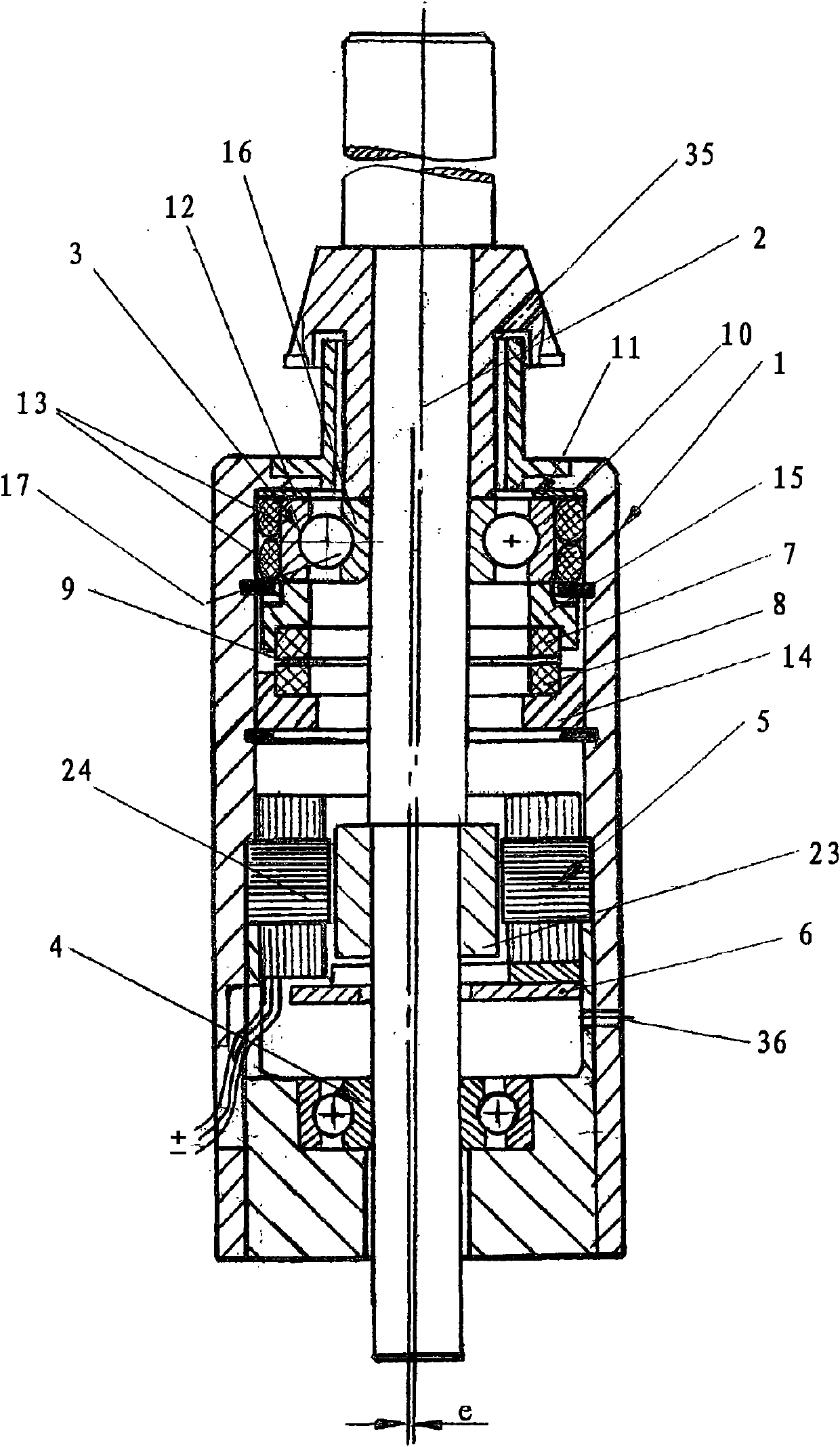
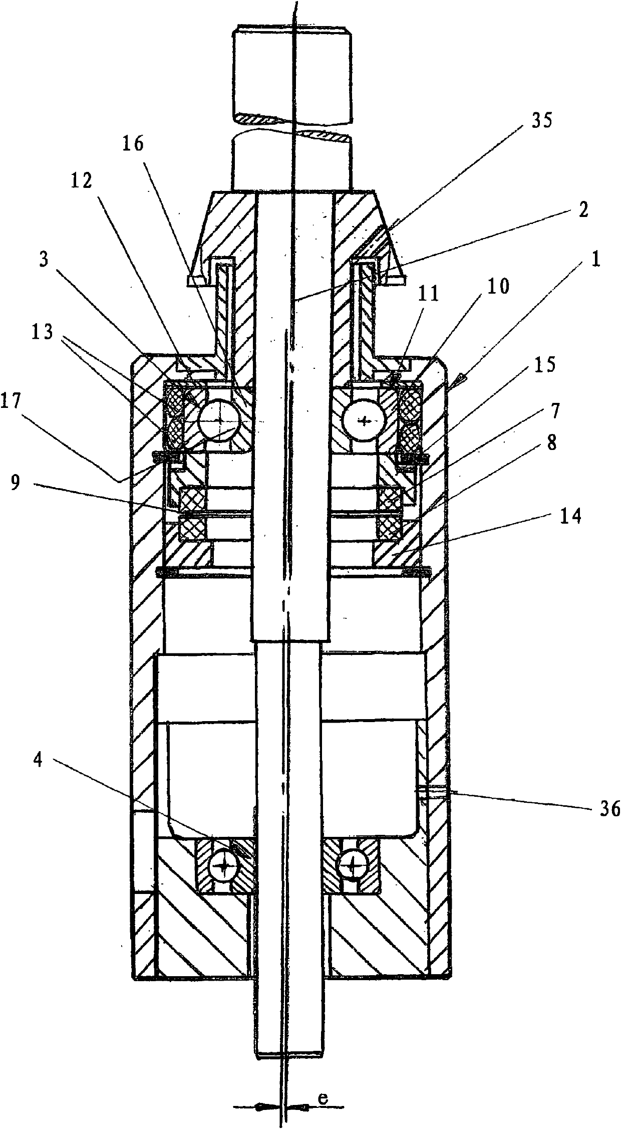
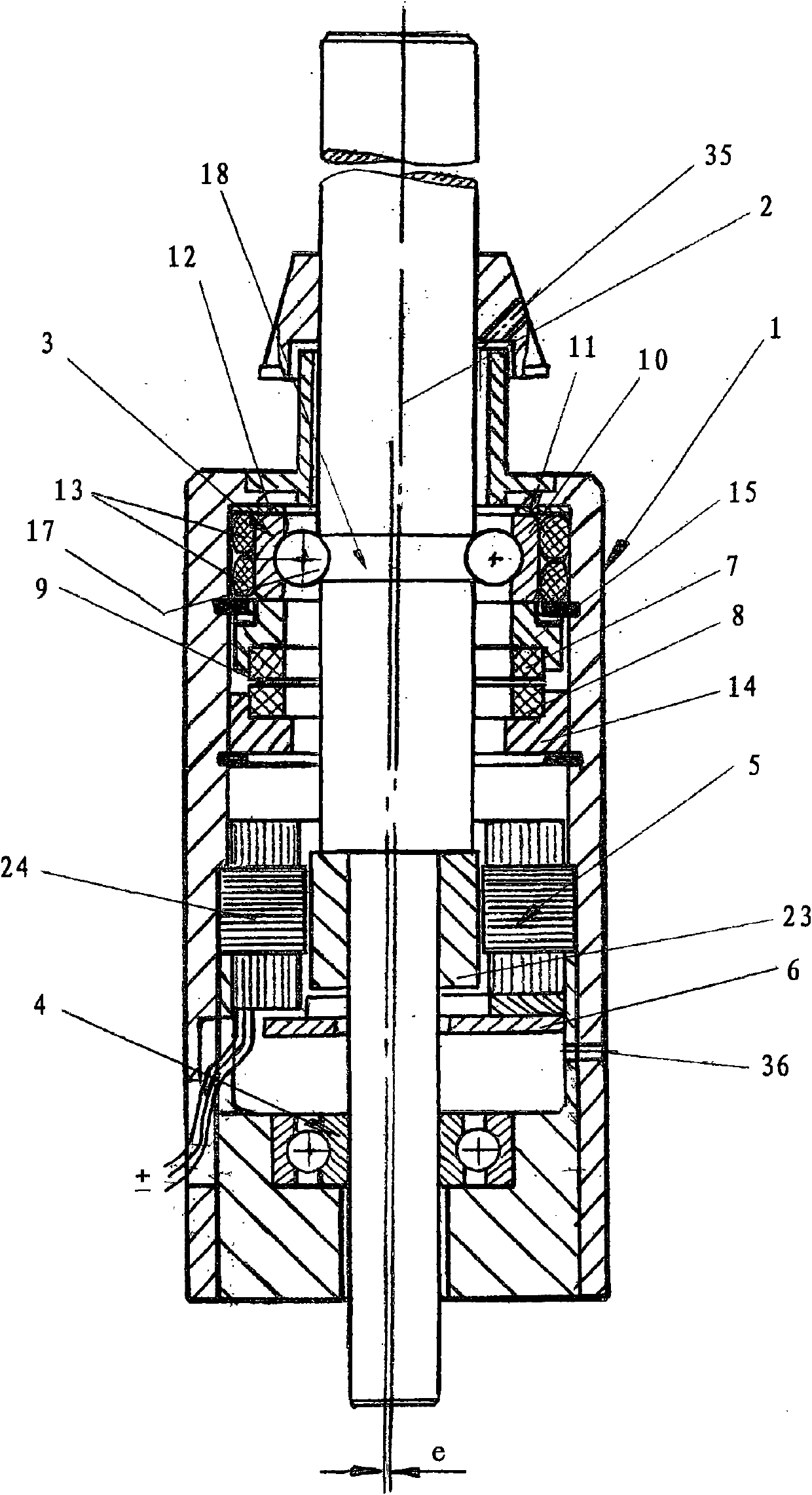
[0019] figure 1 and figure 2 Two embodiments of friction spindles are shown, in which figure 1 and figure 2 The only difference is that figure 1 equipped with an electric motor, and figure 2 There is no electric motor. also, figure 1 and figure 2 It is also shown that the spindle shaft 2 has an eccentricity "e" relative to the outer diameter of the spindle sleeve 1 . In the case of an electric motor integrated between the upper rolling bearing 3 and the lower rolling bearing 4 , the controller of the electric motor is integrated in the electric motor itself.

[0020] also, figure 1 and figure 2 The upper rolling bearing 3 which surrounds the spindle shaft is shown with a so-called damper. The damper is integrated in the figure 1 and figure 2 In the friction equipment, in order to avoid the resonance of the critical speed in the working range of 6000 to 20000 rpm. The shifting of the resonance at a critical speed of 6000 rpm is achieved in that two mutually r...


PUM


Abstract

A frictional false twisting device for deformably combining filament comprises three friction spindles, wherein a distance (B) between axes can be steplessly adjusted with a small scale; the friction spindles according to charts 1 to 5 can be freely adjusted in space; and an arranged damper can influence the resonance of a critical rotate speed so as to keep the resonance is out of the working scope of the friction spindles. Besides, the frictional device can be opened so as to be easily controlled.

Description

technical field [0001] The present invention relates to a friction false twisting device, hereinafter referred to as "friction device", which is used in textile machines (so-called texturing machines) which process synthetically produced filaments from which e.g. women's long Tube socks, swimming and sports clothing, etc. This friction device is a core component of a textile machine. Background technique [0002] There are three friction spindles in the friction device. Hitherto such friction spindles were jointly driven by flat belts, or each friction device was individually driven by an electric motor which drove one of the three spindles via a toothed belt and the two additional spindles via another toothed belt. The toothed belt, which encloses all three spindles, is driven at the same speed. In this way, spindle speeds of 6,000 to 20,000 rpm are produced, depending on the material being processed. In other friction devices driven by electric motors known from the pr...

Claims


Application Information

Patent Timeline
Patent Type & Authority Applications(China)
IPC IPC(8): D02G1/04D02G1/06F16F15/12
Inventor 德特勒夫・格根斯
Owner 德特勒夫·格根斯
Learn More