
Large sealed self aligning roller bearing

a roller bearing, sealed technology, applied in the direction of roller bearings, mechanical equipment, rotary machine parts, etc., can solve the problems of bearings being highly exposed to different kinds of impurities, bearings may, operation, dirt, metal chips, etc., to prevent crack initiation, high tolerance, and easy to form

Active Publication Date: 2015-04-23
AB SKF
View PDF13 Cites 6 Cited by
  • Summary
  • Abstract
  • Description
  • Claims
  • Application Information

AI Technical Summary

Benefits of technology

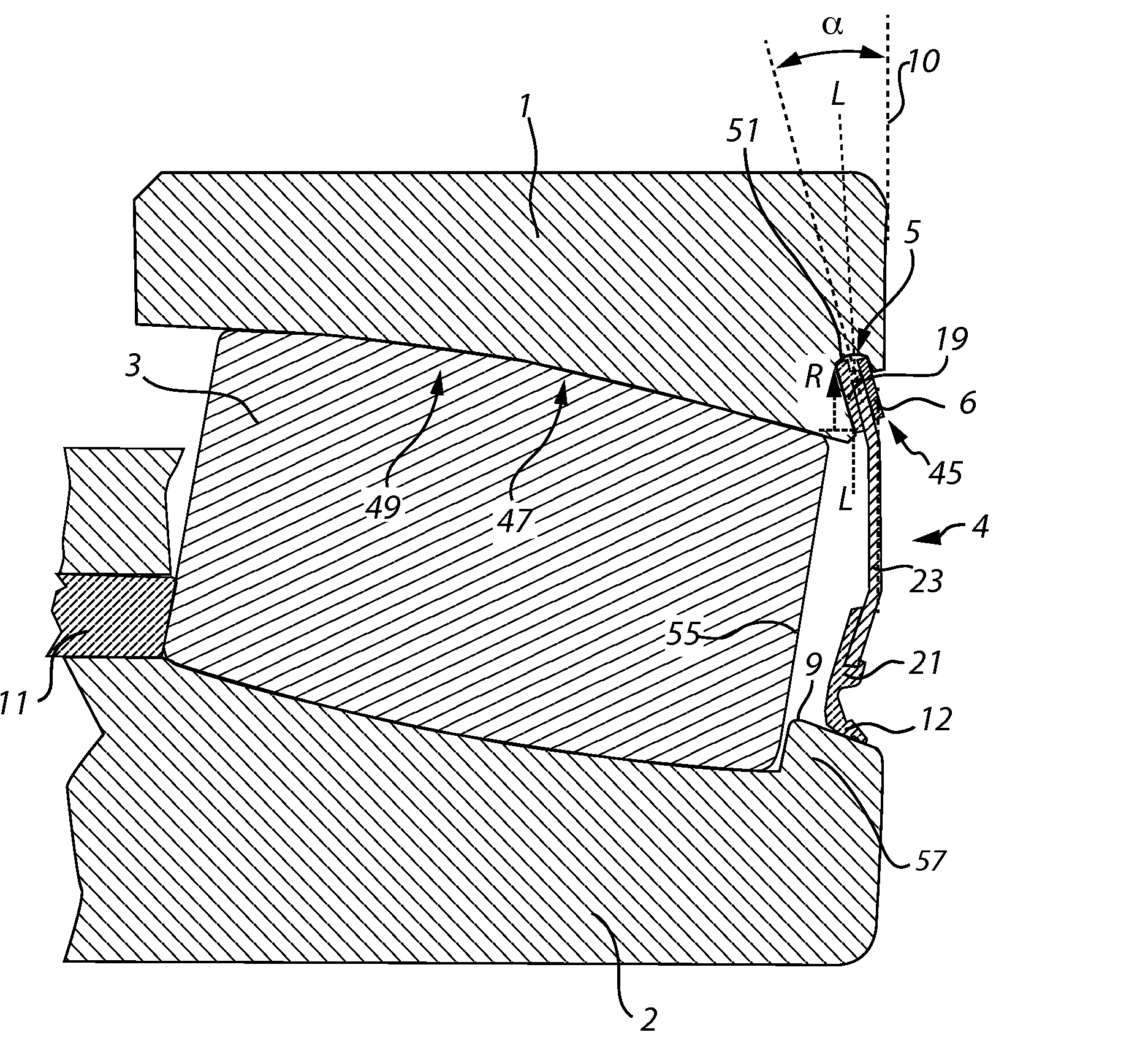
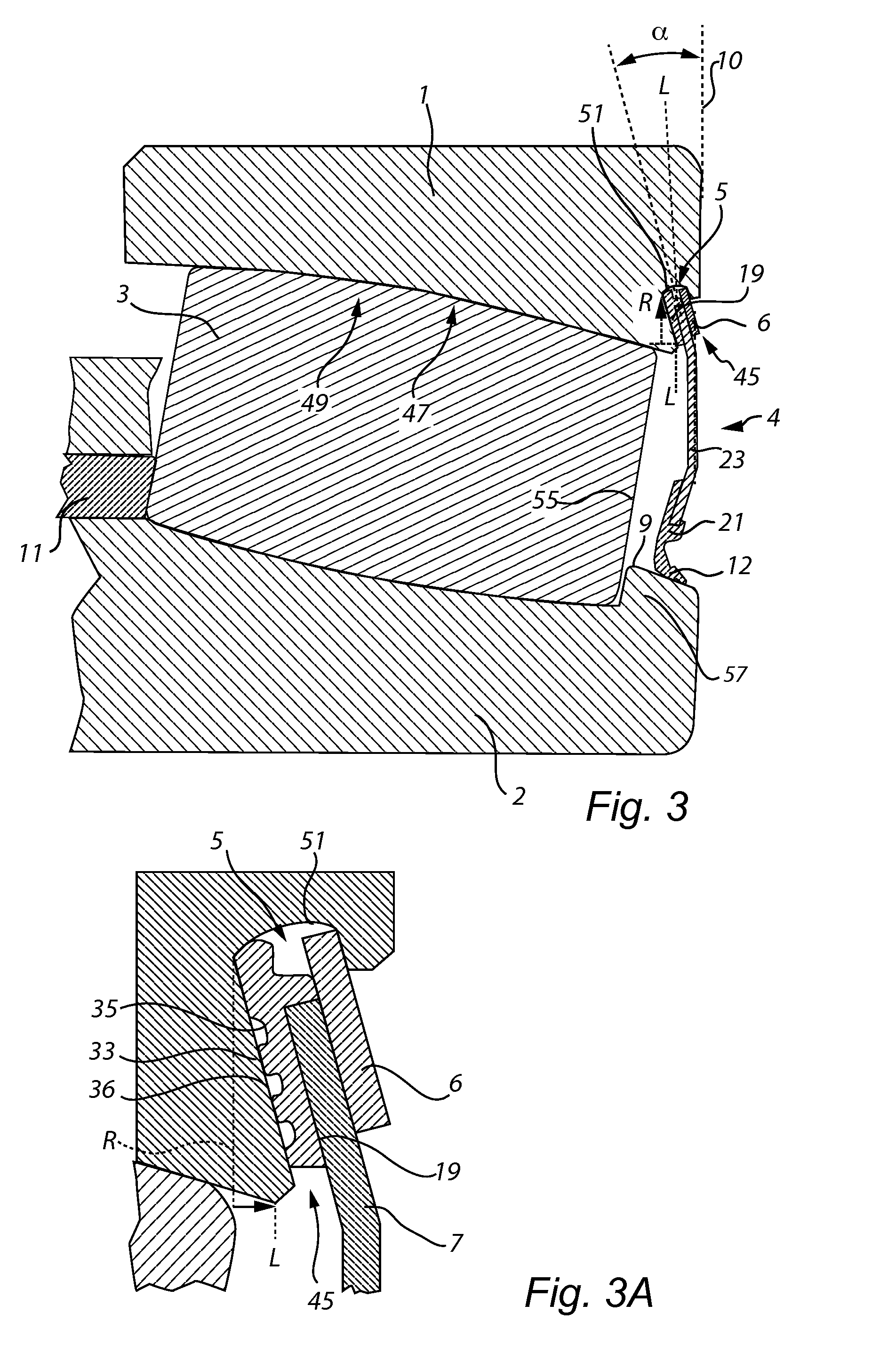
The patent describes a sealing member built into a bearing design. The sealing member is made up of an annular plate ring with a curved or flat shape. The plate ring has one or more bends or knees. The shape of the sealing member is designed to fit tightly into the space between the race rings, reducing the amount of material that sticks out. This design helps to make the bearing more compact. The patent also describes a groove in the first race ring that allows for a more efficient oil flow. Overall, this patent aims to improve the performance and efficiency of bearings.

Problems solved by technology

The mounting of the bearing on one hand may occur in dirty surroundings, and the bearings may, on the other hand during operation, be subjected to dirt, metal chips, etcetera.
At use of bearings in continuous casting machines, in rolling mills, paper making machines, etcetera, the bearings may be highly exposed to different kinds of impurities.
This is furthermore putting high demands on maintenance.
This solution however means that the seal will project outside the side planes, which in some cases necessitates modifications of the bearing housing and also of the mounting and dismantling tools, etcetera.
This solution which has been promising for smaller size bearings has not been used for larger size bearings.
Another reason is that due to the increased requirement of rigidity of the annular plate member need to be thicker, which increases difficulties with forming a spring portion without formation of cracks that may lead to breaking of the annular plate ring.
Large size self aligning bearings are difficult to seal since these bearings are made for handling large angular misalignments.
Further the seal is somewhat sensitive due to the pliable nature of the bellow forming the seal for the bearing.

Method used


Image

  • Large sealed self aligning roller bearing
  • Large sealed self aligning roller bearing
  • Large sealed self aligning roller bearing

Examples


Embodiment Construction

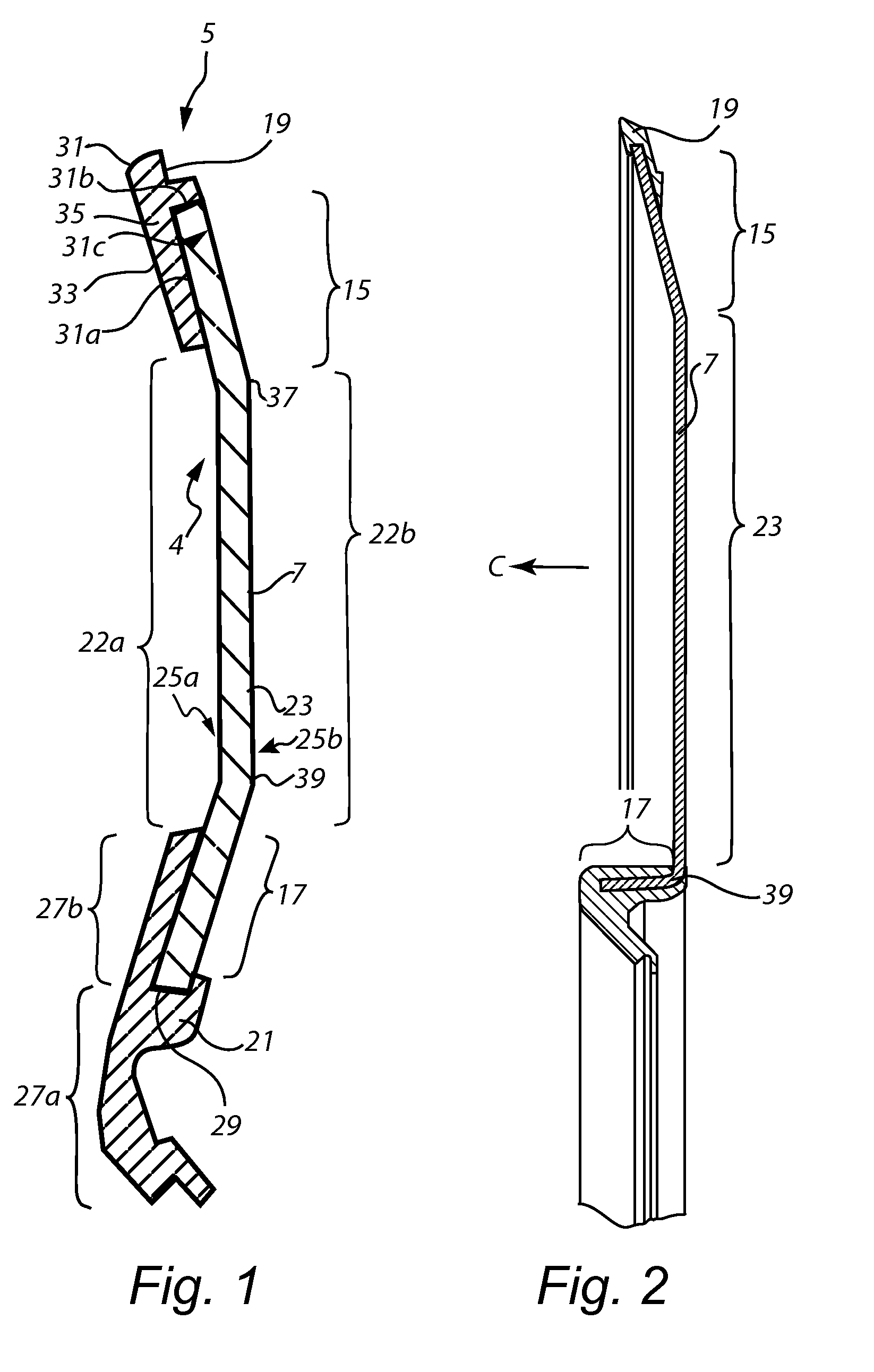
[0051]In FIG. 1 a sealing member is shown. The sealing member shown in FIG. 1 is suitable for a self aligned roller bearing having a cage that does not extend on the outside of the roller. The sealing member 4 includes an annular plate ring 7. The annular plate ring includes a first periphery portion 15 and a second periphery portion 17. A first resilient member 19 is attached to the first periphery portion 15 and a second separate resilient member 21 is attached to the second periphery portion. The first and second separate resilient members 19, 21 are spaced apart to leave an annular land 22a, 22b in a mid section 23 of said annular plate ring 7 in between said first and second resilient members. Preferably the annular land is free from resilient material on both sides of said ring. With both sides is here intended a first inner side 25a facing the interior of the bearing and a second outer side 25b facing the exterior of the bearing.

[0052]The annular land may preferably have a ci...


PUM


Abstract

A large sealed self aligning roller bearing including a first race ring, a second race ring, rolling bodies arranged between the first race ring and the second race ring in one or more rows and a built-in sealing member. The sealing member includes an annular plate ring with a first periphery portion and a second periphery portion. The first ring includes a mounting groove for receiving the first periphery portion and the second race ring includes a sealing surface.

Description

CROSS REFERENCE TO RELATED APPLICATION[0001]This is a National Stage application claiming the benefit of International Application Number PCT / SE2012 / 000198 filed on 10 Dec. 2012 (10.12.2012), which claims the benefit of Sweden Patent Application 1200006-3 filed on 2 Jan. 2012, both of which are incorporated herein by reference in their entireties.TECHNICAL FIELD[0002]The present invention relates to a large sealed self aligning bearing including a first race ring, a second race ring, rolling bodies arranged between the first race ring and the second race ring in one or more rows and a built-in sealing member.BACKGROUND OF THE INVENTION[0003]The service life of a bearing is reduced by dirt and impurities penetrating into the bearing. The mounting of the bearing on one hand may occur in dirty surroundings, and the bearings may, on the other hand during operation, be subjected to dirt, metal chips, etcetera. At use of bearings in continuous casting machines, in rolling mills, paper mak...

Claims


Application Information

Patent Timeline
IPC IPC(8): F16C33/78F16C23/08
CPCF16C33/7823F16C33/7803F16C23/084F16C33/7856F16C33/7806F16C33/783F16C23/086F16C13/02F16C19/38F16C2300/14F16J15/16F16J15/3268F16J15/3272
Inventor ENGSTROM, BENGTSTIGSJOO, LARSSTRAND, PAR
Owner AB SKF
Learn More