
High temperature protective coating

a protective coating and high temperature technology, applied in the direction of coatings, machines/engines, mechanical equipment, etc., can solve the problems of increasing creep, oxidation and/or hot corrosion impact, and affecting the failure mode of parts, so as to improve the tensile strength, improve the ductility of the coating, and improve the effect of properties

Inactive Publication Date: 2017-01-19
ANSALDO ENERGIA IP UK LTD
View PDF2 Cites 1 Cited by
  • Summary
  • Abstract
  • Description
  • Claims
  • Application Information

AI Technical Summary

Benefits of technology

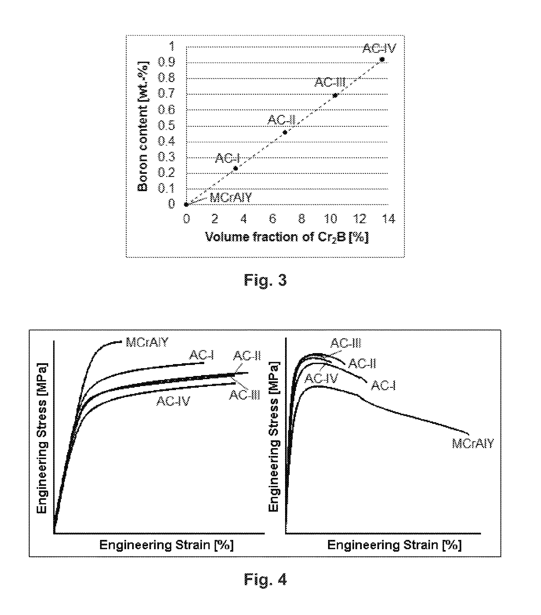
The present invention provides an improved high temperature protective coating for components of turbomachines called MCrAlY. This coating has better properties compared to existing coatings, including higher ductility at lower temperatures and increased tensile strength at higher temperatures. This increase in plastic energy results in a reduction of crack initiation and increased service lifetime in high-cyclic operation modes.

Problems solved by technology

Some components or some specific component areas are prone to fatigue (cyclic loading), while others face increased creep, oxidation and / or hot corrosion impact (base-load).
However, in (high-) cyclic operating gas turbines, the failure mode of the parts is more likely triggered by thermo-mechanic fatigue (TMF).
Standard coatings usually have poor TMF resistance due to their lack of ductility at low temperatures (500° C
The lack of ductility at low temperature is caused by the large amount of fine γ′, β-(NiAl), and α-Cr precipitates (coming from the high content of Al and Cr) limiting the dislocation propagation.
The lack of strength at high temperature is caused by the partial dissolution of the γ′, β-(NiAl), and α-Cr precipitates into the γ matrix, leading to a softening effect and loss of strength.
In γ / γ′ coatings, the transformation of γ′ into β-(NiAl) when increasing the temperature is also an issue, as this is causing a large thermal expansion, leading to stress build-up when used as bond coat and eventually to TBC spallation.
In addition, this is leading to stress accumulation in the coating (overlay) and earlier cracking.
This phenomenon is limiting the maximum working temperature of the coating and / or leading to early failure in cyclic operation.
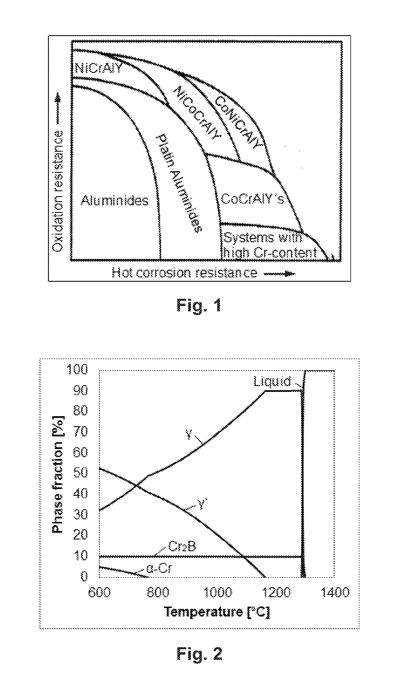
3, and shows very clearly that NiCrAlY coatings have a high oxidation resistance, but as a disadvantage only a low hot corrosion resistance.
But although the formation of β-(NiAl) could be prevented, the coating still suffers from the ductile to brittle transition (DBTT) if operated at elevated temperatures.

Method used


Image

  • High temperature protective coating
  • High temperature protective coating

Examples


Embodiment Construction

[0043]The invention describes an advanced high temperature resistant MCrAlYB coating class containing—as the main factor—the element boron, leading to the formation of chromium-borides, in higher amount (at least 1.75 vol.-% chromium-borides) compared to similar state of the art coatings. M is at least one element out of the group of Ni, Co and Fe. In addition Si and Ta are alloying elements in said MCrAlYB coating according to the invention.

[0044]Some examples of preferred embodiments are coatings consisting of the following elements (given in wt.-%), wherein the balance is always Ni and inevitable impurities:

TABLE 1Chemical composition of several exemplary embodiments of the coating according to the inventionElementCoatingNiCrAlSiTaCoBYAC-IBalance24.025.32.341.241.020.230.45AC-IIBalance23.045.12.081.482.040.460.40AC-IIIBalance22.074.91.821.723.060.690.35AC-IVBalance21.084.71.561.964.080.920.30

[0045]The coating is applied onto the surface of a metallic component, for example a gas ...


PUM

PropertyMeasurementUnit
temperaturesaaaaaaaaaa
temperatureaaaaaaaaaa
volume fractionaaaaaaaaaa

Abstract

The invention relates to a high temperature protective coating based on MCrAlY coating, with M at least one element out of the group of Ni, Co and Fe, for a component of a turbo machine, especially a gas turbine, the coating containing at least at least 1.75 vol.-% chromium borides and the coating consisting of the following chemical composition (in wt.-%): 10-27 Cr; 3-12 Al; 1-4 Si; 0.1-3 Ta; 0.01-3 Y; 0.1-3 B; 0-7 M, with M being a different element out of said group compared to the remainder, and the remainder being M and inevitable impurities. A preferred embodiment is a coating with the following chemical composition: 10-27 Cr; 3-12 Al; 1-4 Si; 0.1-3 Ta; 0.01-3 Y; 0.1-3 B; 0-7 Co and the remainder being Ni and inevitable impurities.

Description

BACKGROUND OF THE INVENTION[0001]The present invention relates to the technology of turbomachines, especially gas turbines. It refers to an advanced high temperature protective coating based on a MCrAlY coating (M=Ni, Co, Fe or combinations thereof) for a component of a turbomachine.PRIOR ART[0002]MCrAlY coatings are commonly applied on hot gas paths components of modern gas turbines. In general, MCrAlY coatings are either applied as an overlay or as a bond coat for thermal barrier coating systems (TBC).[0003]The main target of an overlay is to protect the Ni- / Co-base superalloy substrate from oxidation and hot corrosion. Furthermore, the mechanical integrity of the coating system and of the corresponding base material shall be ensured.[0004]During engine service, the boundary conditions (like e.g. temperature, mechanical stresses, etc.) are different for each component (per stage and even locally on the component). Some components or some specific component areas are prone to fatig...

Claims


Application Information

Patent Timeline
Patent Type & Authority Applications(United States)
IPC IPC(8): C23F11/02C22C19/05C22C19/07
CPCC23F11/02C22C19/058C22C19/07C22C38/005C22C38/02C22C38/06C22C38/26C22C38/32C23C30/00F01D5/288C23C4/073F05D2300/132F05D2300/175F05D2230/31C23C30/005
Inventor SCHAB, JOHANNES CLEMENSZIMMERMANN, JULIEN RENE ANDRESTANKOWSKI, ALEXANDERGRASSO, PIERO-DANIELE
Owner ANSALDO ENERGIA IP UK LTD
Learn More