
Method for heat treating serviced turbine part

a technology for serviced turbines and parts, applied in heat treatment equipment, machines/engines, furnaces, etc., can solve the problems of high temperature and high stress, cracking of hold time, and high stress on gas turbine components or parts, so as to improve the hold time fatigue cracking resistance of serviced turbine parts, reduce surface oxidation, and prevent distortion

Active Publication Date: 2013-10-15
GE INFRASTRUCTURE TECH INT LLC
View PDF20 Cites 1 Cited by
  • Summary
  • Abstract
  • Description
  • Claims
  • Application Information

AI Technical Summary

Benefits of technology

This patent describes a method for improving the resistance of turbine parts to fatigue cracking and growth. The method involves heating the part in a vacuum furnace to prevent distortion and recrystallizing surface damage layers to prevent crack initiation. The part is then cooled to prevent distortion. This method can be applied to serviced turbine parts, such as rotor disks, to increase their durability.

Problems solved by technology

Gas turbine engines operate at high temperatures and high stresses.
Gas turbine components or parts, including, without limitation, rotor disks having wheels and spacers, are subjected to high temperatures and high stresses.
Cracking may result from one or more mechanisms, such as hold time fatigue cracking.
Such hold time fatigue cracking may severely reduce the service life of the gas turbine rotor disks.
However, if the shot peening does not cover the entire surface, cracks may initiate at locations inadequately peened.
In addition, any damage on the surface during handling can cause crack initiation at such locations.
Once the crack is initiated microscopically, the crack may propagate rapidly and make the part unusable.
The obvious disadvantage to this remedy is the required shut down time and the significant time loss.
Further, detection of microscopic cracks by non-destructive methods is difficult and unreliable.
Macroscopic or larger cracks may also be missed in locations difficult to access.
The rapid propagation rate of these cracks may cause failure before the next scheduled inspection.
However, frequent shut down for inspection purposes is highly undesirable for power production turbines, for example.
Such a solution applied to power generation turbines is not desirable because of the cost involved.

Method used


Image

  • Method for heat treating serviced turbine part
  • Method for heat treating serviced turbine part
  • Method for heat treating serviced turbine part

Examples


Embodiment Construction

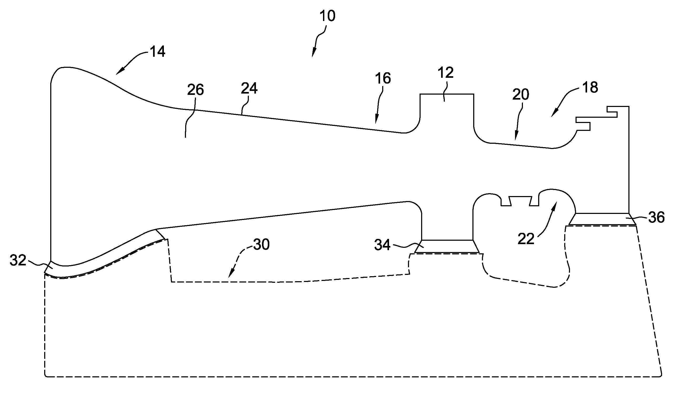
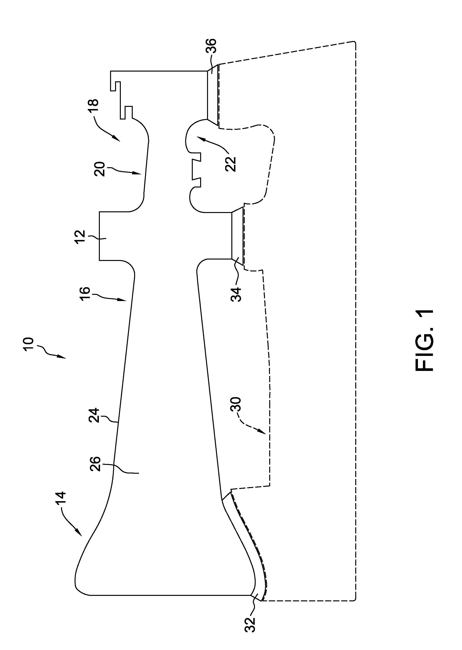
[0011]The present invention provides a method for extending the useful life of a serviced turbine rotor component or part. The method includes a heat treatment process that is applied to a fully-machined, serviced turbine part without causing any damage and / or distortion to the part. The method of the present invention may be used for extending the useful life of any suitable turbine rotor component or part.

[0012]The present invention is described below in reference to its application in connection with and operation of a serviced turbine part and, specifically, to a serviced turbine rotor disk. However, it will be obvious to those skilled in the art and guided by the teachings herein provided that the invention is likewise applicable to any suitable machined, serviced component or part including, without limitation, other components or parts of a turbine engine, a boiler and a heater, and may be applied to systems consuming natural gas, fuel, coal, oil or any solid, liquid or gaseo...


PUM

PropertyMeasurementUnit
temperatureaaaaaaaaaa
holding temperatureaaaaaaaaaa

Abstract

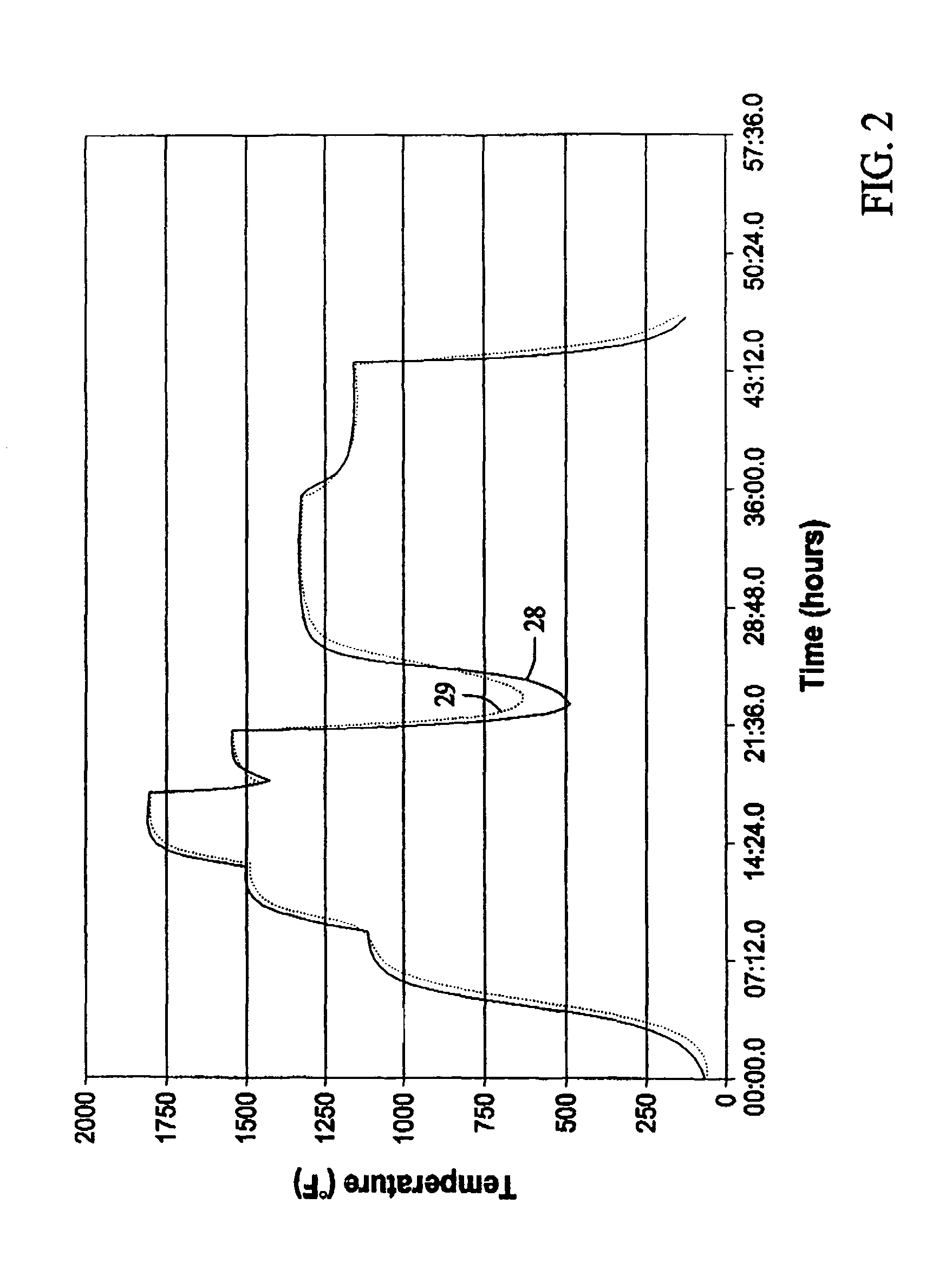
A method for heat treating a serviced turbine part to improve a hold time fatigue cracking resistance of the serviced turbine part is provided. The method includes positioning the serviced turbine part in a vacuum furnace configured to limit surface oxidation. The serviced turbine part is controllably heated to prevent distortion. A surface damage layer is recrystallized into a fine grain structure to prevent fatigue crack initiation. The serviced turbine part is controllably cooled to prevent distortion.

Description

BACKGROUND OF THE INVENTION[0001]This invention relates generally to heat treatment of serviced turbine parts and, more particularly, to a method for extending the useful life of a serviced turbine part.[0002]Gas turbine engines operate at high temperatures and high stresses. Gas turbine components or parts, including, without limitation, rotor disks having wheels and spacers, are subjected to high temperatures and high stresses. The turbine parts are frequently inspected to ensure that cracking is not present in the parts. Cracking may result from one or more mechanisms, such as hold time fatigue cracking. Hold time fatigue cracking occurs as a result of extended in-service hours at high temperatures and / or high stresses and is common among nickel-based alloys, such as Alloy 706. Alloy 706 is a nickel-based superalloy used for high temperature applications in gas turbine engines. Such hold time fatigue cracking may severely reduce the service life of the gas turbine rotor disks.[00...

Claims


Application Information

Patent Timeline
Patent Type & Authority Patents(United States)
IPC IPC(8): C21D8/00F01D5/02C21D9/00B21K25/00
CPCB23P6/002C22F1/18F01D5/005Y10T29/49325F05D2230/90F05D2230/40F05D2250/62
Inventor THAMBOO, SAMUEL V.YANG, LING
Owner GE INFRASTRUCTURE TECH INT LLC
Learn More