Stitch transfer cam of computer knitting machine

A technology of computerized flat knitting machine and transfer cam, which is applied in the field of transfer cam, can solve the problems of high failure rate and complex structure of transfer cam, and achieve the effects of reducing weight, improving knitting effect, reducing manufacturing cost and using cost

Inactive Publication Date: 2011-04-20
NINGBO CIXING
View PDF3 Cites 2 Cited by
  • Summary
  • Abstract
  • Description
  • Claims
  • Application Information

AI Technical Summary

Problems solved by technology

[0003] The invention provides a transfer cam of a computerized flat knitting machine with simple structure and better effect to solve the problems of complex structure and high failure rate of the existing transfer cam

Method used


Image

  • Stitch transfer cam of computer knitting machine
  • Stitch transfer cam of computer knitting machine

Examples


Embodiment Construction

[0012] The present invention will be described in further detail below in conjunction with the accompanying drawings and embodiments.

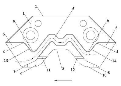
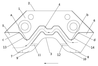
[0013] Referring to the drawings, this embodiment includes a left-right symmetrical body 1 with a straight top edge 2 and a U-shaped bottom edge 3 concave inward; the middle of the body 1 has an M-shaped groove 4. The two ends of the M-shaped groove 4 are oblique grooves extending to both sides of the main body 1 respectively, and the upper sides of the extension parts of the two ends are respectively inclined upward at positions a and b to form a first slope 13 and a second slope 14 , the extended parts of the first and second slopes 13, 14 intersect outwardly with the two sides of the body 1 at c and d respectively, forming two outwardly expanded first bell mouths 5 and second bell mouths 6, thereby penetrating the body 1. Form the needle track.

[0014] There are respectively a first plane 9 and a second plane 10 between the first and seco...


PUM


Abstract

The present invention discloses a stitch transfer cam of computer knitting machine, comprising a body symmetrically left and right, wherein the body has a top edge in a shape of a straight line, and an U-shaped bottom edge concave inwardly; the middle part of the body is provided with an M-shaped groove; two ends of the M-shaped groove respectively extend to two sides of the body and intersect with two sides of the body to form an expanding horn mouth, therefore the groove penetrates through the body. Compared with the prior technology, a plurality of electromagnets, electric control devices and mechanical auxiliary devices can be saved; the structure of a handpiece is simplified, the weight of the handpiece is reduced, and phenomenon that the cam is blocked or is not flexible is avoided; the use of the equipment is more stable and energy is saved; the manufacture cost and use cost are reduced basically; furthermore, the knitting effect of the equipment is improved in a certain extent.

Description

technical field [0001] The invention belongs to the technical field of knitting machinery, in particular to a transfer cam of a computerized flat knitting machine. Background technique [0002] The transfer cam is an important part of the computerized flat knitting machine head. At present, the stitch track design of domestic computerized flat knitting machines is generally through the up and down switching of the Zhongshan triangle and the transfer guide block, and the transfer guide block cooperates with the sharp mountain to form the running track of the stitches during transfer. When knitting garment pieces, according to the needs of the pattern process, the knitting cam and the transfer cam often switch their actions, and some corresponding pressing tablets also need to change their positions. Whether it is the action of the triangle or the change of the tablet pressing position, it must be completed by a flexible auxiliary mechanism under the control of an electromagn...

Claims


Application Information

Patent Timeline
Patent Type & Authority Applications(China)
IPC IPC(8): D04B15/36
Inventor 孙平范
Owner NINGBO CIXING
Why Eureka
Try Eureka