Electronic shift device

A traverse device and traverse technology, applied to the device used on warp knitting machines, in the field of electronic traverse devices, can solve the problems of short service life, unfavorable maintenance, unfavorable arrangement of the bar, and achieve maintenance prevention, simple structure and cost. low effect

Inactive Publication Date: 2011-04-20
CHANGZHOU WUJIN WUYANG TEXTILE MACHINERY
View PDF0 Cites 11 Cited by
  • Summary
  • Abstract
  • Description
  • Claims
  • Application Information

AI Technical Summary

Problems solved by technology

The nut cannot rotate with the screw rod because it is fixed on the ejector rod parallel to the screw rod, but it can move linearly along the screw rod. Arrangement of combs

Method used


Image

  • Electronic shift device
  • Electronic shift device
  • Electronic shift device

Examples


Embodiment Construction

[0016] The present invention will be further described below in conjunction with the accompanying drawings and specific embodiments.

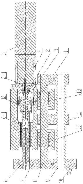
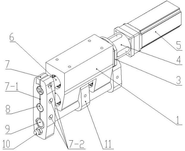
[0017] See attached figure 1 , attached figure 2 , an electronic traversing device, including a servo motor 5 and a mover, a traversing tight ring 7, the mover includes a main mover and an auxiliary mover, and a spherical plug 10 is arranged on the end face of the traversing tight ring 7.

[0018] The main mover includes a guide seat 1, a connecting flange 1 3, a connecting flange 2 4, a ball screw 2, a ball nut 12 and a propulsion shaft 6, the connecting flange 1 3 is fixed on one end of the guiding seat 1, and the connecting flange The second 4 is connected with the servo motor 5, and the connecting flange one 3 is fixedly connected with the connecting flange two 4; The ring 7 is fixed, and there is a cavity 6-1 inside the other end. The ball screw 2 and the ball nut 12 sleeved on it are fixed in the cavity 6-1. The ball screw 2 passes thr...


PUM


Abstract

The invention relates to an electronic shift device, comprising a servo motor, a locomotory apparatus and a shift straining ring, wherein the locomotory apparatus comprises a main locomotory apparatus and an assistant locomotory apparatus, and the servo motor is fixedly installed on the main locomotory apparatus; the main locomotory apparatus comprises a guide holder, a connecting flange, a ball screw, a ball nut and a propeller shaft, wherein the connecting flange is fixedly installed on one end of the guide holder to be connected with the servo motor; the shift staining ring is positioned on the other end of the guide holder; the propeller shaft is positioned in the guide holder, one end of the propeller shaft is fixed with the shift straining ring, and a cavity is formed in the other end of the propeller shaft; the ball screw and the ball nut are fixed in the cavity; and the ball screw is connected with the connecting flange by a screw shaft on the end of the ball screw. The assistant locomotory apparatus comprises a spring shaft, a transition shaft, a linear bearing and an assistant straining ring, wherein one end of the spring shaft is fixed with the shift straining ring, the other end of the spring shaft is fixedly arranged on the assistant straining ring, and the transition shaft is installed in the guide holder by the linear bearing. The invention is favorable for ensuring product quality and maintenance, prevents dust from entering, has low cost, and simple and compact structure and improves the service life of products.

Description

technical field [0001] The invention relates to a device used on a warp knitting machine, in particular to an electronic traverse device, which belongs to the field of textile machinery. Background technique [0002] The control device of the electronic traversing device on the original warp knitting machine is composed of a face plate or a chain block, which has the advantages of slow speed, small traversing distance, complicated pattern change, high cost of pattern change, poor traversing accuracy (with cumulative errors), and poor operation. It has disadvantages such as cumbersome, large space occupation and high noise. And the control device of existing electronic traverse mainly is made up of servo motor, screw mandrel, nut and ejector rod, and nut is sleeved on the screw mandrel, and one end of ejector rod is fixedly connected with nut one side, and the other end of ejector rod is connected with electronic comb. The nut cannot rotate with the screw rod because it is f...

Claims


Application Information

Patent Timeline
Patent Type & Authority Applications(China)
IPC IPC(8): D04B27/26
Inventor 王敏其赵志初
Owner CHANGZHOU WUJIN WUYANG TEXTILE MACHINERY
Why Eureka
Try Eureka