Suction fan impeller of mower

A technology for exhaust fans and lawn mowers, which is applied in the directions of machines/engines, mechanical equipment, liquid fuel engines, etc., can solve problems such as affecting the mowing efficiency of combined lawn mowers and not being suitable for cutting weeds.

Active Publication Date: 2011-04-20
河南新路航交通科技有限公司
View PDF5 Cites 42 Cited by
  • Summary
  • Abstract
  • Description
  • Claims
  • Application Information

AI Technical Summary

Problems solved by technology

There is also a large-scale combined lawn mower, the main structure of which is that the engine drives the blades to rotate to cut grass, and the engine drives the exhaust fan to rotate to generate negative pressure to collect the cut grass. The blades of the exhaust fan impeller of this lawn mower In order to be twisted into a plate-shaped structure at a certain angle, during the mowing process, a lot of cut grass is entangled on the blades. After running for a period of time, the mower needs to stop to clean the grass on the blades before continuing the mowing operation. Mowing Efficiency to Combine Mowers
[0004] The above three lawn mowers are not suitable for cutting the uneven weeds on both sides of the airport runway, contact road and taxiway.

Method used


Image

  • Suction fan impeller of mower
  • Suction fan impeller of mower
  • Suction fan impeller of mower

Examples


Embodiment 1

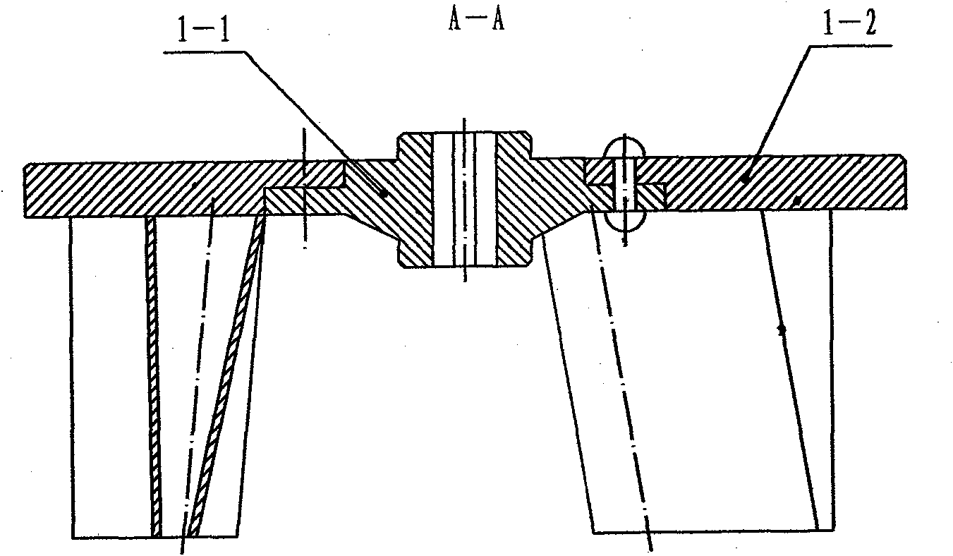
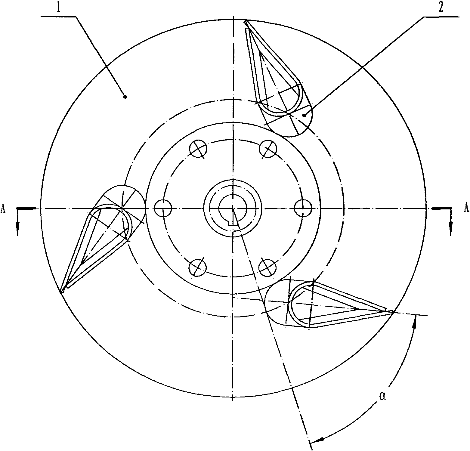
[0019] exist figure 1 , 2 Among them, the exhaust fan impeller of the lawn mower in this embodiment is composed of a disc 1 and a blade 2 connected.

[0020] The wheel disk 1 of this embodiment is composed of a hub 1-1 and a blade disk 1-2. The outer edge of the wheel hub 1-1 is connected with the blade disk 1-2 by rivets to form the wheel disk 1, and the wheel hub 1-1 and the blade disk 1-2 can also be fixedly connected by threaded fasteners. On the blade disk 1-2 of the wheel disk 1, three blades 2 are evenly distributed and welded, the inner end of the blade 2 overlaps the outer end of the hub 1-1, and the center line of the blade 2 is tangent to the inner end of the blade 2. The angle α between the diameters is 60°.

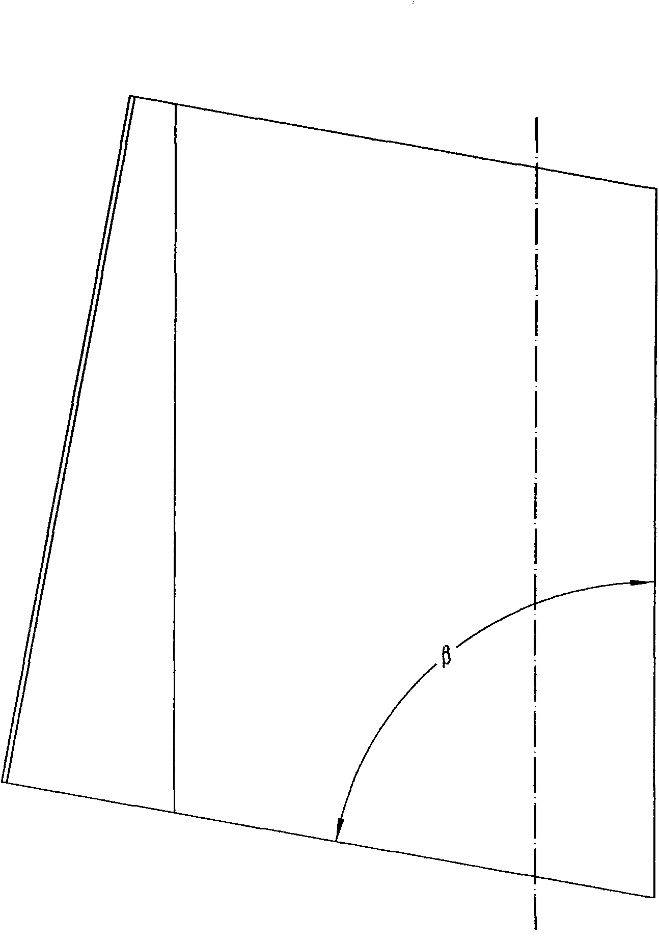
[0021] image 3 , 4 A schematic structural view of the blade 2 of this embodiment is given. exist image 3 , 4 Among them, the blade 2 of this embodiment is made by welding the outer end of the front side and the inner surface of the rear side after a...

Embodiment 2

[0023] In this embodiment, the number of welded blades 2 on the blade disk 1 - 2 of the wheel disk 1 and the included angle α between the center line of the blade 2 and the diameter tangent to the inner end are the same as those in Embodiment 1. The blade 2 of this embodiment is made by welding the outer end of the front side and the inner surface of the rear side after a piece of steel plate is crimped. The angle β is 50°. The rear side of blade 2 is trapezoidal, and the outside edge of trapezoid is perpendicular to base, and the plane where the upper base of trapezoid and the upper base of parallelogram is parallel to the plane where the lower base of trapezoid and the lower base of parallelogram are. The included angle γ between the anteromedial inner surface and the posterior inner inner surface of the blade 2 is 20°. The inner end of the blade 2 is a circular arc surface with a radius R of 15mm that is tangent to the front outer surface and the rear outer surface and is ...

Embodiment 3

[0025] In this embodiment, the number of welded blades 2 on the blade disk 1 - 2 of the wheel disk 1 and the included angle α between the center line of the blade 2 and the diameter tangent to the inner end are the same as those in Embodiment 1. The blade 2 of this embodiment is made by welding the outer end of the front side and the inner surface of the rear side after a piece of steel plate is crimped. The angle β is 80°. The rear side of blade 2 is trapezoidal, and the outside edge of trapezoid is perpendicular to base, and the plane where the upper base of trapezoid and the upper base of parallelogram is parallel to the plane where the lower base of trapezoid and the lower base of parallelogram are. The angle γ between the front inner surface and the rear inner surface of the blade 2 is 45°. The inner end of the blade 2 is a circular arc surface with a radius R of 30mm that is tangent to the front outer surface and the rear outer surface and is connected as a whole. Othe...


PUM


Abstract

The invention relates to a suction fan impeller of a mower, which is characterized in that blades are arranged on a wheel disc. In the wheel disc, the periphery of a hub is provided with a blade disc, 2-4 blades are uniformly distributed on the blade disc, the inner ends of the blades are in overlap joint with the outer end of the hub, and the included angle Alpha between the center lines of the blades and the diameter which is tangential to the inner ends is 30-80 degrees; in the blades, the front side surfaces of the blades are shaped as a parallelogram, the included angle Beta between the inner side edge and the bottom edge of the parallelogram is 50-80 degrees; the back side surfaces of the blades are shaped as a trapezoid, the outer side edge of the trapezoid is perpendicular to the bottom edge, the plane in which the upper bottom edge of the trapezoid and the upper bottom edge of the parallelogram are located is parallel to the plane in which the lower bottom edge of the trapezoid and the lower bottom edge of the parallelogram are located; the included angles Gamma between the front side surfaces and the back side surfaces of the blades are 20-45 degrees; the inner ends of the blades are an integrated circular arc surface with radius of 15-30 millimeters which is tangential to the front outer side surfaces and the back outer side surfaces; and the outer ends of the front side surfaces of the blades are coupled with the inner surfaces of the back side surfaces.

Description

technical field [0001] The invention belongs to the technical field of mowing equipment or devices, and in particular relates to parts of a mowing machine. Background technique [0002] On both sides of the airport runway, contact road, and taxiway, weeds grow vigorously in the hot summer season, and the height is uneven. Some grass grows very high, and some grass grows low. The runway, contact road, taxiway The weeds on both sides of the airport block the lights on both sides of the airport runway, contact road and taxiway, which affects flight safety. These weeds need to be cut and cleaned regularly. [0003] There are mainly three types of lawn mowers currently on the market. One is a large-scale lawn mower, which is driven by the engine to rotate the blades to mow grass. This kind of lawn mower is mainly used for mowing grass on grasslands. Then collect them back and store them for later use. Large-scale lawn mowers cannot cut low weeds, and the weeds cannot be cleaned ...

Claims


Application Information

Patent Timeline
Patent Type & Authority Applications(China)
IPC IPC(8): F04D29/28F04D29/30
Inventor 聂伟聂红聂绍社张建利
Owner 河南新路航交通科技有限公司
Why Eureka
Try Eureka