Single-direction and double-direction clutch mechanism

A two-way clutch and cam technology, applied in the field of mechanical transmission, can solve the problems of high processing difficulty, easy deformation of the compression spring, high cost, and achieve the effect of reducing processing cost and easy processing.

Active Publication Date: 2011-04-20
左佳奇
View PDF7 Cites 10 Cited by
  • Summary
  • Abstract
  • Description
  • Claims
  • Application Information

AI Technical Summary

Problems solved by technology

When the power output part of the clutch (inner ring or outer ring) rotates faster than the power source (outer ring or inner ring), the clutch is in a disengaged state, and the inner and outer rings have no interlocking relationship. This is the overrunning function of the clutch, based on Therefore, the overrunning clutch function of the overrunning clutch mechanism is realized. Because the current one-way device is mainly a spline cam type overrunning clutch, the patent number is ZL03233130.4, and the name is "a speed change gear device with a cam type overrunning characteristic". Disclosed is a one-way clutch, which includes a gear, and a spline cam is installed at the center of the gear. The circumference of the spline cam is evenly distributed with a plurality of smooth curved surfaces with lifting characteristics, and there is a gap between the spline cam and the inner diameter of the gear. There are rollers in the evenly divided notch of the cage, and each roller corresponds to a smooth curved surface of the spline cam with lifting characteristics; a device is installed between the cage and the spline cam to make the cage The roller squeezes to the elastic mechanism in the direction of the cam lift, and the elastic mechanism is a compression spring. This structure mainly has the following disadvantages: First, when it is overrun, the compression spring is easy to deform, shrinks and cannot rebound and fails, resulting in one-way Second, the processing of this structure is complicated, especially for the processing of the cage. The installation position of the compression spring and the installation steps of the cam need to be processed in the cage, so the processing is difficult and the cost is high.

Method used


Image

  • Single-direction and double-direction clutch mechanism
  • Single-direction and double-direction clutch mechanism
  • Single-direction and double-direction clutch mechanism

Examples


Embodiment 1

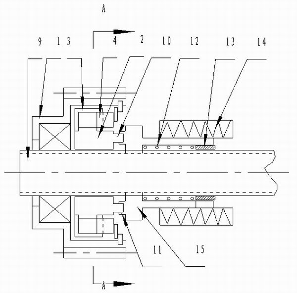
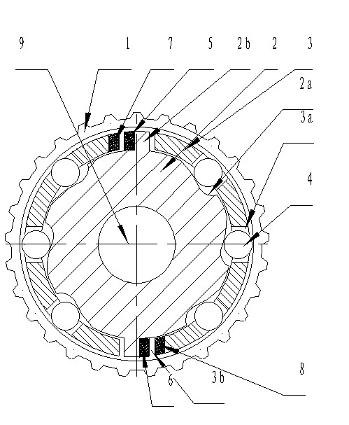
[0028] Such as figure 1 , figure 2 , image 3 , Figure 10 and Figure 11 The one-way and two-way clutch mechanism shown includes a gear 1, the left part of the gear 1 is sleeved on the transmission shaft 9 through a bearing, and a cam 2 is installed at the center of the right part of the gear 1, and the cam 2 is looped on the transmission shaft 9 Above, a floating sleeve 3 is installed between the cam 2 and the inner wall of the gear 1, and a set of cam curved surfaces 2a and two bosses 2b are arranged on the outer circumference of the cam 2, and the set of cam curved surfaces 2a and two bosses Columns 2b are evenly distributed on the outer circumference of the cam 2, and the two convex columns 2b are arranged oppositely, wherein the cam curved surfaces 2a are all smooth curved surfaces with lift characteristics, and each cam curved surface 2a is along the reverse direction. Clockwise is distributed on the outer circumference of the cam 2, of course, each cam curved surf...

Embodiment 2

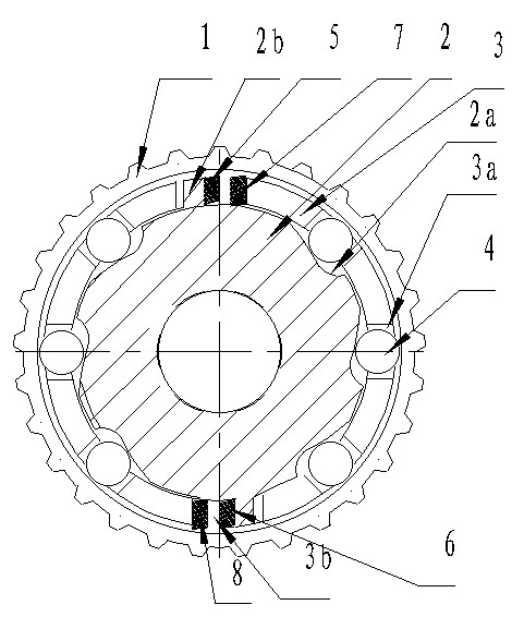
[0030] Such as Figure 4 , Figure 5 , Figure 6 , Figure 10 and Figure 11 The one-way and two-way clutch mechanism shown includes a gear 1, the left part of the gear 1 is sleeved on the transmission shaft 9 through a bearing, and a cam 2 is installed at the center of the right part of the gear 1, and the cam 2 is looped on the transmission shaft 9 Above, a floating sleeve 3 is installed between the cam 2 and the inner wall of the gear 1, and a set of cam curved surfaces 2a and two bosses 2b are arranged on the outer circumference of the cam 2, and the set of cam curved surfaces 2a and two bosses Columns 2b are evenly distributed on the outer circumference of the cam 2, and the two convex columns 2b are arranged oppositely, wherein the cam curved surfaces 2a are all smooth curved surfaces with lift characteristics, and each cam curved surface 2a is along the reverse direction. Clockwise is distributed on the outer circumference of the cam 2, of course, each cam curved su...

Embodiment 3

[0032] Such as Figure 7 , Figure 8 , Figure 9 , Figure 10 and Figure 11 The one-way and two-way clutch mechanism shown includes a gear 1, the left part of the gear 1 is sleeved on the transmission shaft 9 through a bearing, and a cam 2 is installed at the center of the right part of the gear 1, and the cam 2 is looped on the transmission shaft 9 Above, a floating sleeve 3 is installed between the cam 2 and the inner wall of the gear 1, and a set of cam curved surfaces 2a and two bosses 2b are arranged on the outer circumference of the cam 2, and the set of cam curved surfaces 2a and two bosses Columns 2b are evenly distributed on the outer circumference of the cam 2, and the two convex columns 2b are arranged oppositely, wherein the cam curved surfaces 2a are all smooth curved surfaces with lift characteristics, and each cam curved surface 2a is along the reverse direction. Clockwise is distributed on the outer circumference of the cam 2, of course, each cam curved su...


PUM


Abstract

The invention discloses a single-direction and double-direction clutch mechanism. In the single-direction and double-direction clutch mechanism, a group of cam curved surfaces are arranged on the outer circumference of a cam; the cam curved surfaces are smooth curved surfaces with lift characteristics; each cam curved surface is distributed on the outer circumference of the cam in the same rotating direction; pin roller mounting gaps corresponding to the cam curved surfaces are reserved on a floating sleeve; pin rollers are arranged in the pin roller mounting gaps; magnetic steel is arranged between the floating sleeve and the cam; the floating sleeve can push the pin rollers to the lift direction of the cam curved surfaces through the magnetic steel; a clamping platform is arranged on any end face of the cam; a ratchet platform mechanism with a ratchet platform is fixedly sleeved on a driving shaft on the outer side of the clamping platform; and the ratchet platform is clamped with the clamping platform. The ratchet platform mechanism is singly arranged, so that single-direction and double-direction overrunning clutch can be realized well.

Description

technical field [0001] The invention belongs to the technical field of mechanical transmission, and in particular relates to a one-way or two-way clutch mechanism capable of realizing one-way or two-way clutch. Background technique [0002] In the existing overrunning clutch mechanism, one of the important parts is the one-way device of the spline cam with the spline groove, because the one-way device can make a certain element only rotate in a certain direction and lock in another direction. When the power output part of the clutch (inner ring or outer ring) rotates faster than the power source (outer ring or inner ring), the clutch is in a disengaged state, and the inner and outer rings have no interlocking relationship. This is the overrunning function of the clutch, based on Therefore, the overrunning clutch function of the overrunning clutch mechanism is realized. Because the current one-way device is mainly a spline cam type overrunning clutch, the patent number is ZL0...

Claims


Application Information

Patent Timeline
Patent Type & Authority Applications(China)
IPC IPC(8): F16D41/08
Inventor 左佳奇
Owner 左佳奇
Why Eureka
Try Eureka