Vertical gas fired boiler

A gas-fired boiler and vertical technology, which is applied in the field of vertical gas-fired atmospheric hot water boilers, can solve the problems of large gas consumption, small heat exchange area, and low thermal efficiency

Inactive Publication Date: 2011-04-20
曲沃县秀水炉业有限公司
View PDF9 Cites 8 Cited by
  • Summary
  • Abstract
  • Description
  • Claims
  • Application Information

AI Technical Summary

Problems solved by technology

[0003] In order to overcome the shortcomings of existing vertical gas-fired atmospheric boilers with small heat exchange area, low thermal efficiency...

Method used


Image

  • Vertical gas fired boiler
  • Vertical gas fired boiler
  • Vertical gas fired boiler

Examples


Embodiment 1

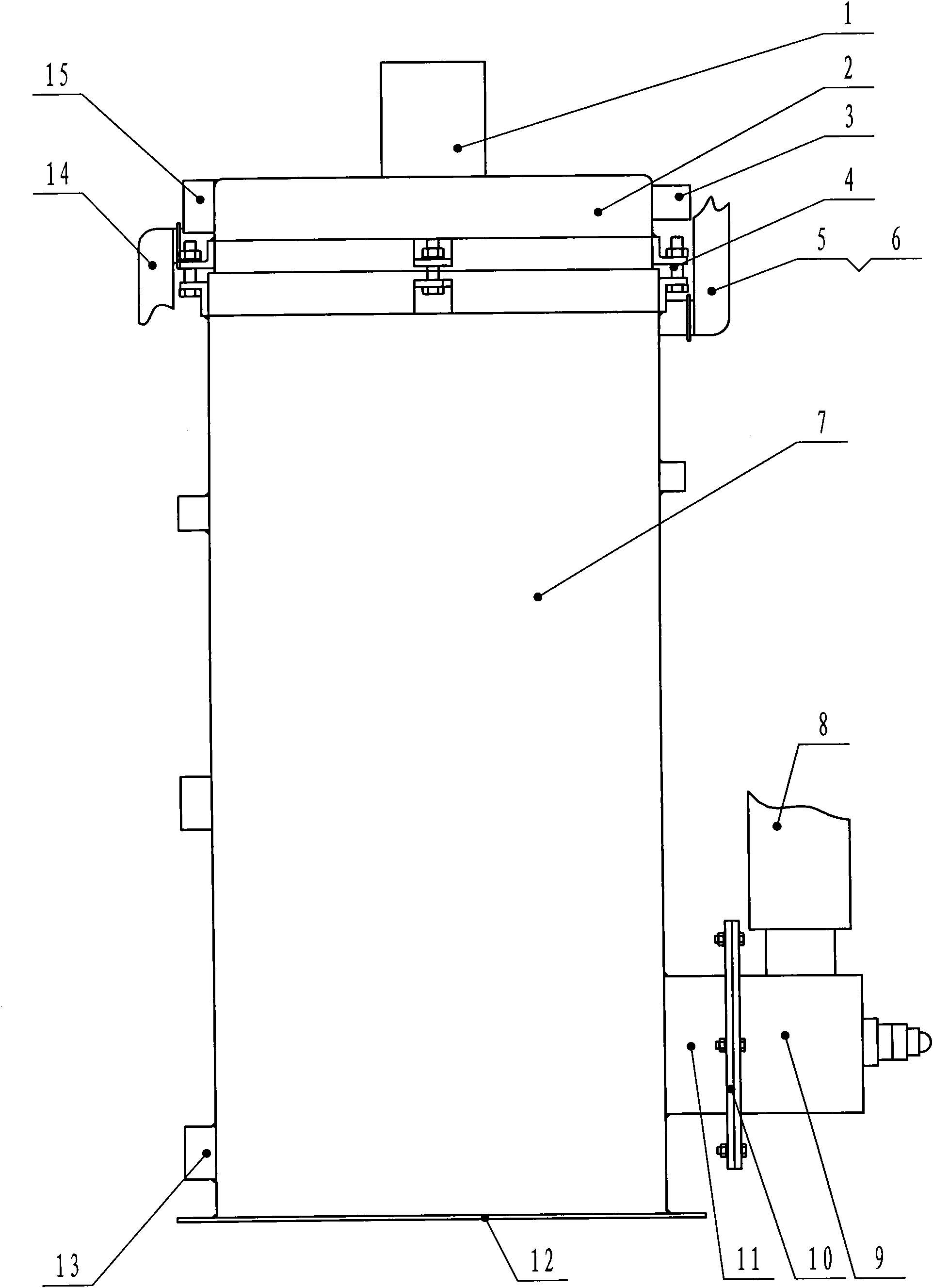
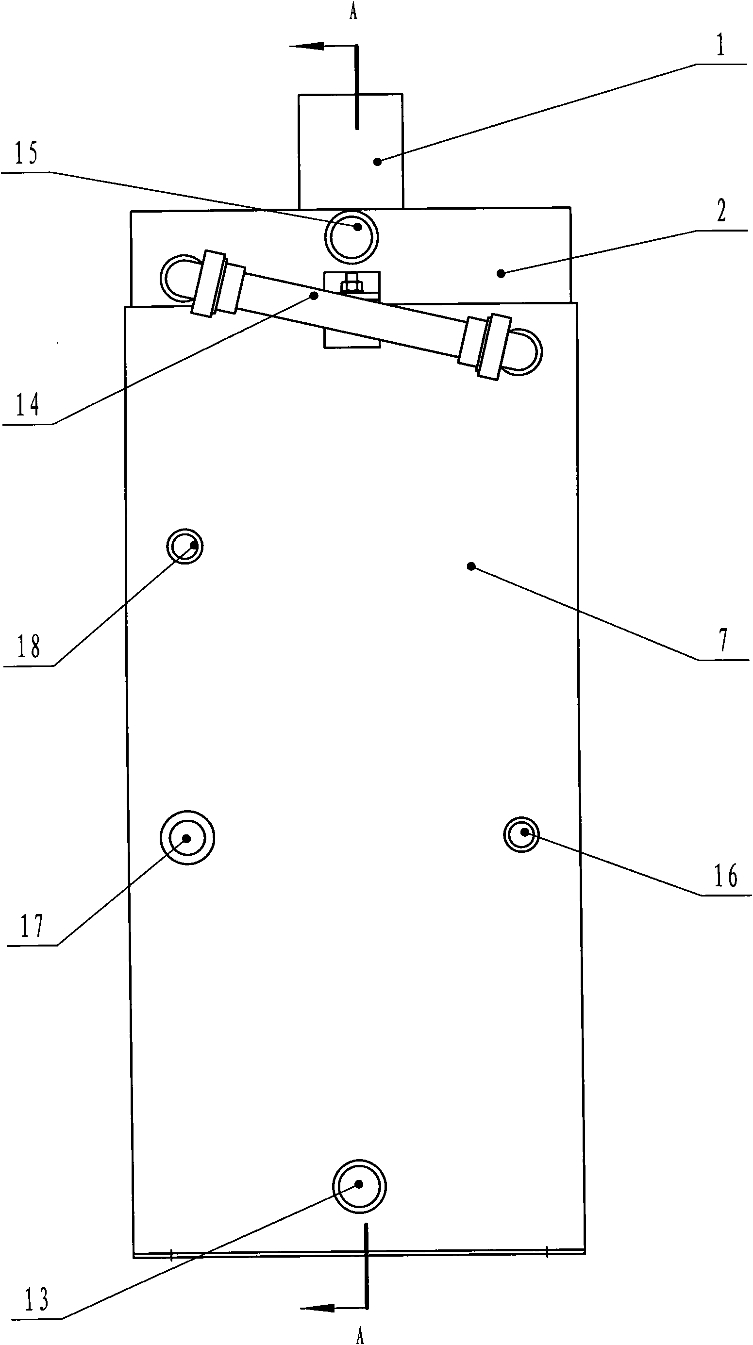
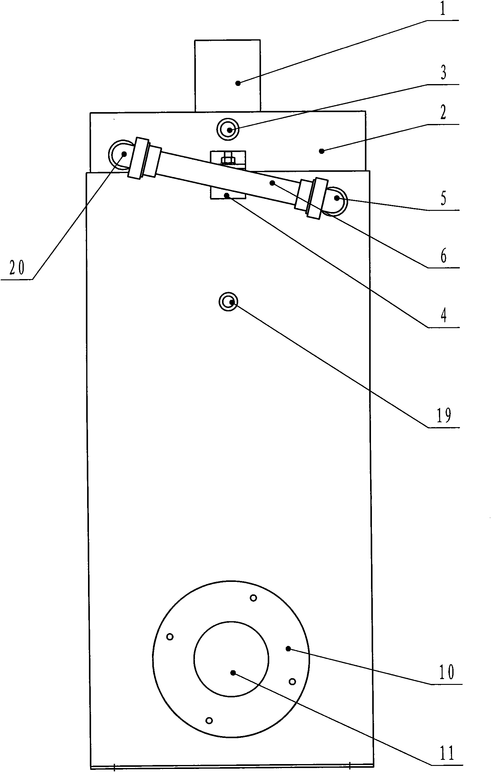
[0045] figure 1 , figure 2 , image 3 and Figure 4The described vertical gas boiler includes a chimney 1, a smoke exhaust cover 2, a furnace outer tank 25, a water chamber 24, a fire tube 34, a furnace and a furnace door pipe 11, the chimney 1 is welded on the smoke exhaust cover 2, and the smoke exhaust cover 2 Be installed on the top of the outer bladder 25 and be fastened together by fasteners, the return pipe 13 and the furnace door pipe 11 are fixed at the outer bladder 25, and the outer bladder 25 is the base 12. Four upper side plates 37 forming a circle are welded inside the outer furnace bladder 25, the interval between the outer furnace bladder 25 and the upper side plates 37 constitutes the upper interlayer water jacket 22, and the upper end of the upper interlayer water jacket 22 is closed. The upper flower plate 23 of the distribution through hole is welded under the upper side plate 37 in the outer furnace 25, and the upper furnace 21 is formed between the s...

Embodiment 2

[0053] The structure of this embodiment is simpler than that of Embodiment 1, and it is easier to popularize. It just installs the water pipe in the fire pipe of the existing vertical gas boiler, see Figure 10 . It includes a chimney 58, a smoke exhaust cover 59, an outer furnace bladder 69, a water chamber 70, a fire pipe 85, a furnace 81 and a furnace door pipe 74. The chimney 58 is welded on the smoke exhaust cover 59, and the smoke exhaust cover 59 is installed outside the furnace The top of the gallbladder 69 is fastened together by fastening bolts 63 and hexagonal nuts 64, and there is an insulating material 60 between the outer casing and the inner casing of the smoke exhaust cover 59. Backwater pipe 78 and furnace door pipe 74 are fixed at outer furnace 69, and base 75 is under the outer furnace 69. Four upper side plates 67 are welded on the inner side of the outer bladder 69, the interval between the outer bladder 69 and the upper side plate 67 constitutes an uppe...


PUM


Abstract

The invention relates to a vertical gas fired boiler, comprising a chimney, a smoke venting cover, an outer boiler furnace, water jackets, a fire tube, hearths and a boiler door tube, wherein the chimney is welded on the smoke venting cover; the smoke venting cover is installed at the top of the outer boiler furnace; an upper hearth is formed between the lower part of the smoke venting cover and each of an upper side plate and an upper embossed plate; the outer boiler furnace is internally provided with the fire tube; a lower hearth is positioned in an inner boiler furnace; the boiler door tube is communicated with the lower hearth; the gap between the periphery of the inner boiler furnace and the outer boiler furnace forms a lower interlayer water jacket; an upper interlayer water jacketis communicated with the upper part of a water containing cavity; and the lower part of the water containing cavity is communicated with the lower interlayer water jacket. The vertical gas fired boiler is characterized in that the fire tube is internally provided with a water tube, the upper hearth is internally provided with an upper horizontal water tube, the lower hearth is internally providedwith a lower horizontal water tube, the upper end of the water tube is welded on the through hole of the upper horizontal water tube, and the lower end of the water tube is welded on the through holeof the lower horizontal water tube. A water interlayer and a horizontal water tank can also be arranged on the smoke venting cover. The vertical gas fired boiler has large heat exchange area and highthermal efficiency.

Description

technical field [0001] The invention relates to a vertical gas boiler, in particular to a vertical gas normal pressure hot water boiler. Background technique [0002] With the increase of urban and rural building areas, the demand for gas-fired atmospheric boilers also increases. Vertical gas-fired atmospheric boilers occupy a small area and are suitable for urban and rural households. The existing vertical gas-fired atmospheric boilers are all fire-tube gas-fired atmospheric boilers, and the interlayer of the smoke exhaust cover is made of heat-insulating materials, so the heat has not been fully utilized. The heat exchange area actually used for the heating system is small, and the exhaust gas temperature High temperature (160℃~250℃), low thermal efficiency and large gas consumption. Contents of the invention [0003] In order to overcome the shortcomings of the existing vertical gas-fired atmospheric boilers with small heat exchange area, low thermal efficiency and lar...

Claims


Application Information

Patent Timeline
IPC IPC(8): F24H1/44
Inventor 郭秀水
Owner 曲沃县秀水炉业有限公司
Why Eureka
Try Eureka