Refrigerator

A technology for refrigerators and heat-insulated boxes, which is applied in the field of blower refrigerators, which can solve the problems of reducing the rigidity of side panels, increasing the space occupied by refrigerators, and deteriorating appearance, so as to improve heat dissipation performance and realize the effect of power consumption

Active Publication Date: 2011-04-20
HITACHI APPLIANCES INC
View PDF5 Cites 22 Cited by
  • Summary
  • Abstract
  • Description
  • Claims
  • Application Information

AI Technical Summary

Problems solved by technology

[0004] In the above-mentioned conventional refrigerator, although the opening in the side of the machine room can be well ventilated into the machine room, if the opening is formed only in the side panel, the side panel is deformed, and when placed so that the side of the refrigerator can be seen , the appearance deteriorates
[0005] In addition, in the above-mentioned conventional refrigerator, although it is disclosed that the opening is formed with a plurality of holes to improve the rigidity of the side panel, since the plurality of openings are simply opened only on the flat surface of the side panel, the opening The rigidity of the side panels will inevitably be lowered, making it difficult to secure reliability in the strength of the main body of the refrigerator
[0006] In addition, in the above-mentioned conventional refrigerator, by providing the air path that constitutes the opening with a plurality of holes and protrudes from the side panel to the outside of the opening, although the air flow of the compressor installed in the above-mentioned machine room that is transmitted from the opening to the outside of the refrigerator is reduced, Noise, but because the air duct is set to protrude from the side panel, the appearance of the refrigerator will be worse, and the space occupied by the refrigerator will also increase

Method used


Image

  • Refrigerator
  • Refrigerator
  • Refrigerator

Examples


Embodiment Construction

[0027] Embodiments of the present invention will be described below using the drawings.

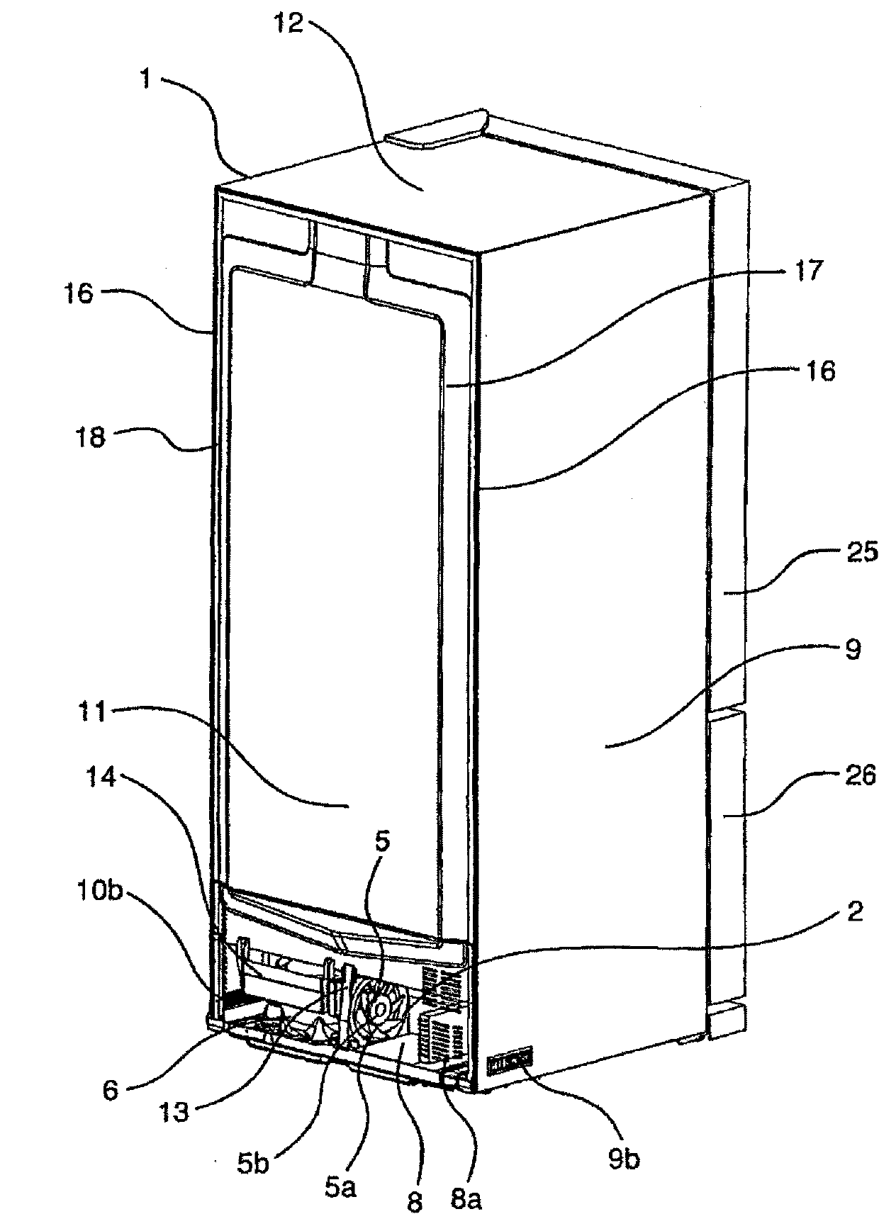
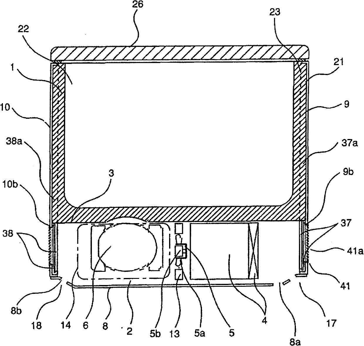
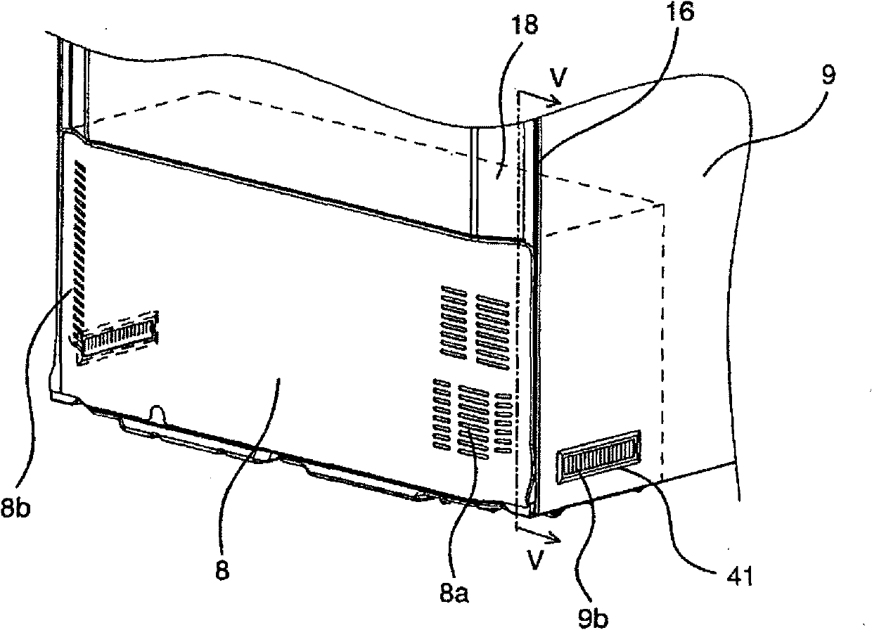
[0028] First, refer to Figure 1 to Figure 6 The overall structure and operation including air flow of this embodiment will be described. Figure 7 and Figure 8 The arrows in indicate the flow of air, Figure 4 The arrows at indicate the flow of refrigerant.

[0029] Such as figure 1 and figure 2 As shown, the main body 1 of the refrigerator includes: an outer case 21 formed of a top plate 12 forming an outer surface, side panels 9, 10, a back panel 11, a main body bottom plate 3, etc.; an inner case 23 forming a storage room 22; Heat insulating materials 24 such as heat insulating polyurethane foam filled between the inner boxes 23 . The outer case 21 is made of a metal plate such as a steel plate, and the inner case 23 is made of a synthetic resin such as ABS resin. A plurality of doors 25 and 26 for opening and closing a plurality of storage compartments 22 are provided on the...


PUM


Abstract

The invention provides a refrigerator, which is characterized in that, a side surface opening of a mechanical chamber is disposed such that deformation of a side surface plate and protruding of an air path will not influence appearance and ventilation with good effect is provided to the mechanical chamber, therefore improving heat dissipation performance of a compressor and a condenser, and realizing reduction of consumption electric quantity. The refrigerator is provided with a heat insulation box with heat insulation performance; a mechanical chamber disposed at the back surface lower part of the insulation box body; a compressor and a condenser disposed in the mechanical chamber; an opening disposed at the side wall of the mechanical chamber; an air blower disposed in the mechanical chamber and conveying air in a width direction of the heat insulation box body; a reinforcing member disposed from the lower part to the back part of the mechanical chamber; a first keep part keeping the lower part of the reinforcing member at the bottom of the mechanical chamber; and a second part keeping the back surface part of the reinforcing member to the upper part or the back part of the mechanical chamber, the side wall of the mechanical chamber clamps with the upper wall and the inner side all of the mechanical chamber, the two ends of the bottom of the mechanical chamber clamp with thelower part of the side wall or the reinforcing member located at the lower part of the side wall.

Description

technical field [0001] The present invention relates to a refrigerator, in particular to a refrigerator suitable for arranging a compressor, a condenser, and a blower for ventilating them in a machine room. Background technique [0002] As a conventional refrigerator, for example, there is a refrigerator disclosed in JP-A-8-285439. If described in terms used in the description of the embodiments of the present invention, the refrigerator includes: a machine room provided at the lower corner of the back of the refrigerator body; a compressor arranged in the machine room; and a blower arranged in the machine room and ventilated to the compressor and the condenser. The side panels on both sides of the machine room are formed with openings for sucking in air and for discharging air. And, the opening is formed only on both sides of the machine room, and one or more openings are formed. The operation of the blower draws outside air through one opening, discharges the air from th...

Claims


Application Information

Patent Timeline
Patent Type & Authority Applications(China)
IPC IPC(8): F25D23/10F25D17/04
Inventor 广田明久盐野谦治
Owner HITACHI APPLIANCES INC
Why Eureka
Try Eureka