Front-end fence using line terminator and electronic impulse detector using front-end fence

An electronic pulse and detector technology, which is applied in the direction of alarms, instruments, alarms, etc. by breaking/disturbing the straightened rope/metal wire, which can solve the problem of inability to guarantee the pressure difference between the two adjacent wires, the host terminal There are many problems such as the loss of the alarm function of the electronic guardrail, so as to achieve the effect of reducing the number of host terminals and simplifying the structure of the host.

Inactive Publication Date: 2013-12-18
上海睿堡电子科技发展有限公司
View PDF3 Cites 1 Cited by
  • Summary
  • Abstract
  • Description
  • Claims
  • Application Information

AI Technical Summary

Problems solved by technology

[0005] 1. There are many wiring terminals on the host, and at least 4 wiring terminals are required
[0006] 2. The 6-wire system cannot guarantee the pressure difference between two adjacent wires, such as figure 1 As shown, the high-voltage detection lines 1 and 2 are equipotential
When the thief short-circuits the detection line along the dotted line, cut off the outer branch detection high-voltage line at the X-shaped position of the front-end fence of the detection, then the high-voltage detection line can cross the fence and ensure the normal passage of the front-end fence, that is, the output pulse signal returns to the detection input through the short-circuited circuit. The detection end cannot know that the detection high-voltage line has been cut off, so the electronic fence loses its alarm function

Method used


Image

  • Front-end fence using line terminator and electronic impulse detector using front-end fence
  • Front-end fence using line terminator and electronic impulse detector using front-end fence
  • Front-end fence using line terminator and electronic impulse detector using front-end fence

Examples


Embodiment Construction

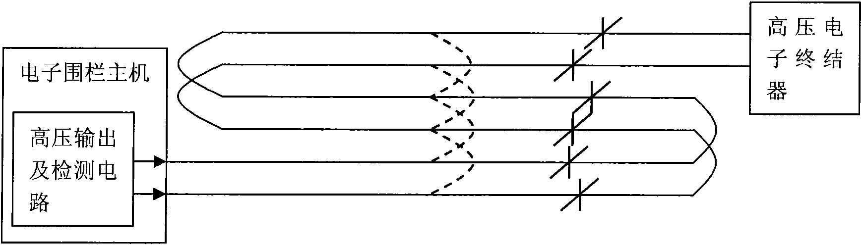
[0032] The present invention is described further below by embodiment, and its purpose is for better understanding content of the present invention. Therefore, the examples given do not limit the protection scope of the present invention:

[0033] Front fence of the present invention and the electronic pulse type detector using it, as image 3 As shown, the host 2 includes a high-voltage rectifying and filtering circuit. The high-voltage output circuit has two outputs of high-voltage pulse signals, and the two outputs are connected to an electronic circuit terminator to form a loop. The electronic circuit terminator is a self-made high voltage inductor. The inductance and the capacitance between the high-voltage lines, that is, the spatially distributed capacitance formed by the long high-voltage lines, are connected in parallel to form a filter network. The inductance value matches the capacitance value. For high-voltage electronic pulses, the filter network is a high-resi...


PUM


Abstract

The invention relates to a front-end fence, in particular to a front-end fence using a line terminator and an electronic impulse detector using the front-end fence. The front-end fence comprises a high voltage detection line which is connected in series with an electronic line terminator; and the electronic impulse detector comprises the front-end fence and an electronic fence host, wherein the electronic fence host comprises a high-voltage rectifier filter circuit and a microcontroller for judging the output signals of the high-voltage rectifier filter circuit, the high-voltage rectifier filter circuit comprises at least two input ends and an output end, the input end is connected with the front-end fence which is connected in series with the electronic line terminator, and the output ends are both connected with the microcontroller. Through the structure of the front-end fence in the invention, the number of host terminals is reduced, thereby simplifying the structure of the host; high voltage and other potential problems existing in 6-wire (or above) electronic fences are solved; and the difficult problem of alarm failure caused by illegal bypass is also solved.

Description

technical field [0001] The invention relates to a front fence and an electronic pulse detector, in particular to a front fence using a line terminator and an electronic pulse detector using the same. technical background [0002] The electronic fence is currently the most advanced perimeter anti-theft alarm system, which consists of a high-voltage electronic pulse host and a front-end detection fence. The high-voltage electronic pulse host generates and receives high-voltage pulse signals, and can generate alarm signals when the front-end detection fence is in the state of touching the net, short circuit, or open circuit, and sends the intrusion signal to the security alarm center; the front-end detection fence is composed of poles and metal wires, etc. The physical perimeter of components. The electronic fence is an active intrusion anti-surpassing fence, which counters the intrusion attempt, repels the intruder, delays the intrusion time, and does not threaten human life,...

Claims


Application Information

Patent Timeline
Patent Type & Authority Patents(China)
IPC IPC(8): G08B13/00G08B13/12
Inventor 常会君
Owner 上海睿堡电子科技发展有限公司
Why Eureka
Try Eureka