
Method for improving chip cutting

A chip and cutting process technology, which is applied in the field of integrated circuit chip cutting, can solve problems such as chip failure and chip characteristic influence, and achieve the effects of reducing pollution, improving quality and output, and suppressing effects

Active Publication Date: 2013-02-20
SEMICON MFG INT (SHANGHAI) CORP +1
View PDF0 Cites 0 Cited by
  • Summary
  • Abstract
  • Description
  • Claims
  • Application Information

AI Technical Summary

Problems solved by technology

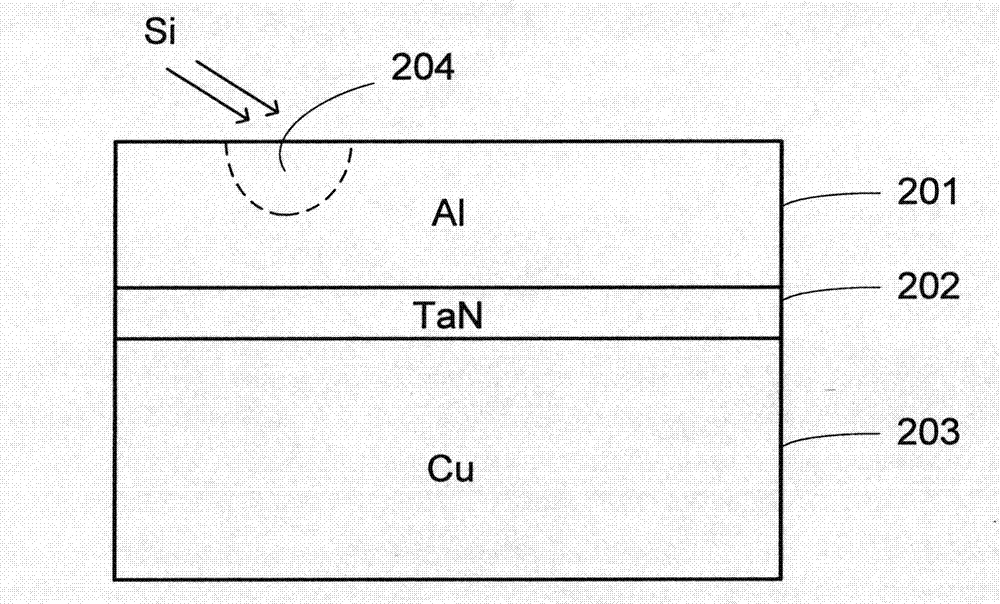
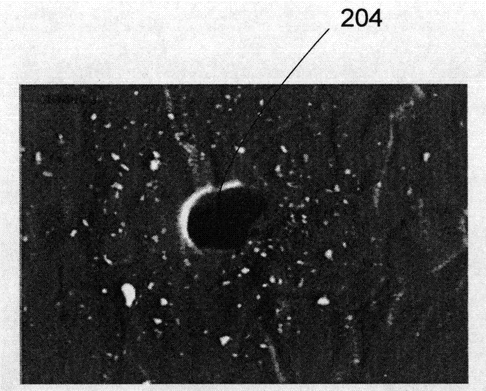
The high-viscosity jelly produced by the reaction adheres to the surface of the pad and is difficult to be washed off, thus affecting the characteristics of the chip, and in severe cases will lead to chip failure

Method used


Image

  • Method for improving chip cutting
  • Method for improving chip cutting
  • Method for improving chip cutting

Examples


Embodiment Construction

[0024] In the following description, numerous specific details are given in order to provide a more thorough understanding of the present invention. It will be apparent, however, to one skilled in the art that the present invention may be practiced without one or more of these details. In other examples, some technical features known in the art are not described in order to avoid confusion with the present invention.

[0025] In order to thoroughly understand the present invention, detailed steps will be presented in the following description to illustrate how the present invention reduces the contamination of the bonding pads by improving the chip dicing method. Obviously, the practice of the invention is not limited to specific details familiar to those skilled in the semiconductor arts. Preferred embodiments of the present invention are described in detail below, however, the present invention may have other embodiments besides these detailed descriptions.

[0026] refer ...


PUM

PropertyMeasurementUnit
thicknessaaaaaaaaaa
thicknessaaaaaaaaaa

Abstract

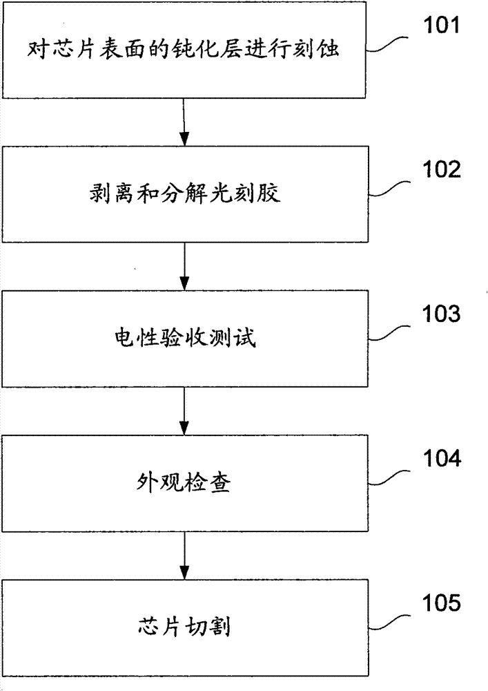
The invention discloses a method for improving a chip cutting process. The method comprises the following steps of: coating photoresist on a passivation layer on the surface of a chip to be cut; etching the passivation layer on the surface of the chip to expose the surface of a solder pad, and peeling the photoresist; and oxidizing an exposed metal layer to produce a metal oxide layer. The method also comprises the steps of: performing an electric acceptance test on the chip; checking the appearance of the chip; and cutting the chip. According to the method of the invention, the cutting of the chip is improved, thus the pollution of silicon dust on the solder pad, especially pollution on a surface Al layer is reduced, and the galvanic effect is inhibited.

Description

technical field [0001] The invention relates to an integrated circuit chip cutting method, in particular to a chip cutting method for reducing AlCu welding pad pollution. Background technique [0002] Die cutting has always been a very important process in the semiconductor industry. After a semiconductor wafer (wafer) has gone through a complicated manufacturing process, it needs to be divided into several small circuit chips, that is, chips. If the high yield rate cannot be maintained during the chip separation stage, or the original characteristics of the chip are affected by the chip separation method, or the cutting speed is too slow and the cost is too high, it will have a very serious impact on the production of the entire chip. [0003] figure 1 The flow of conventional chip dicing is shown. In step 101, a layer of photoresist with a pattern is covered on the surface of the chip, and the passivation layer located on the outermost surface of the chip is etched. In...

Claims


Application Information

Patent Timeline
Patent Type & Authority Patents(China)
IPC IPC(8): H01L21/78H01L21/321H01L27/02G03F7/00
Inventor 张京晶王会卿
Owner SEMICON MFG INT (SHANGHAI) CORP
Learn More