Method, device and system for sharing network
A technology for sharing network and system messages, applied in the field of shared network
- Summary
- Abstract
- Description
- Claims
- Application Information
AI Technical Summary
Problems solved by technology
Method used
Image
Examples
Embodiment 1
[0023] This embodiment includes the following steps: in the MOCN cell of the multi-operator core network, broadcast a system message including multiple PLMNs corresponding to multiple operators and reflecting the priority relationship between multiple PLMNs; receiving the message sent by the user terminal UE According to the PLMN selected by the system information; according to the PLMN selected by the UE, route the UE to the core network corresponding to the selected PLMN.
[0024] Among them, the priority relationship between multiple PLMNs can be reflected in various ways. Method 1: In the system message, multiple PLMNs have a preset arrangement order, for example, one or a certain PLMN can be arranged at the top as required, indicating that the priority of this PLMN is higher than that of other PLMNs. Mode 2: In the system message, each PLMN of multiple PLMNs has a priority level.
[0025] Further, if multiple PLMNs include a common PLMN shared by multiple operators, diff...
Embodiment 2
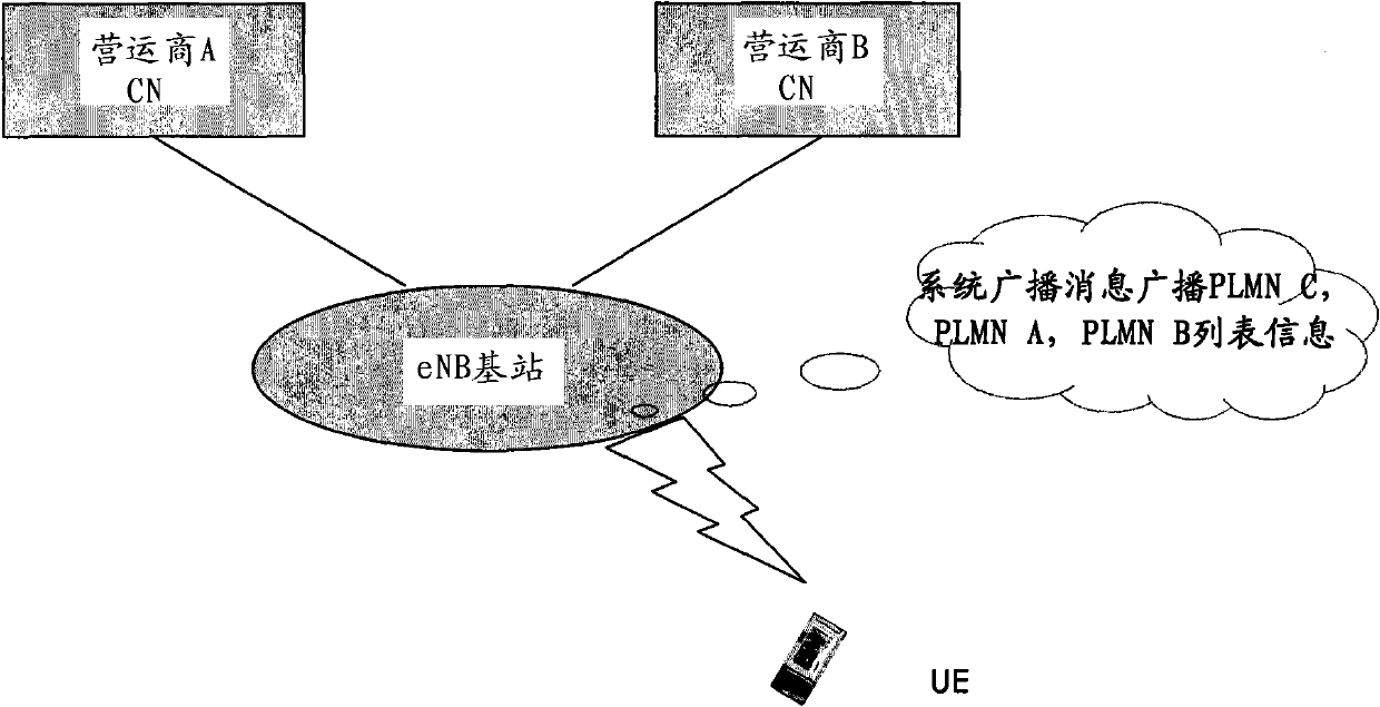
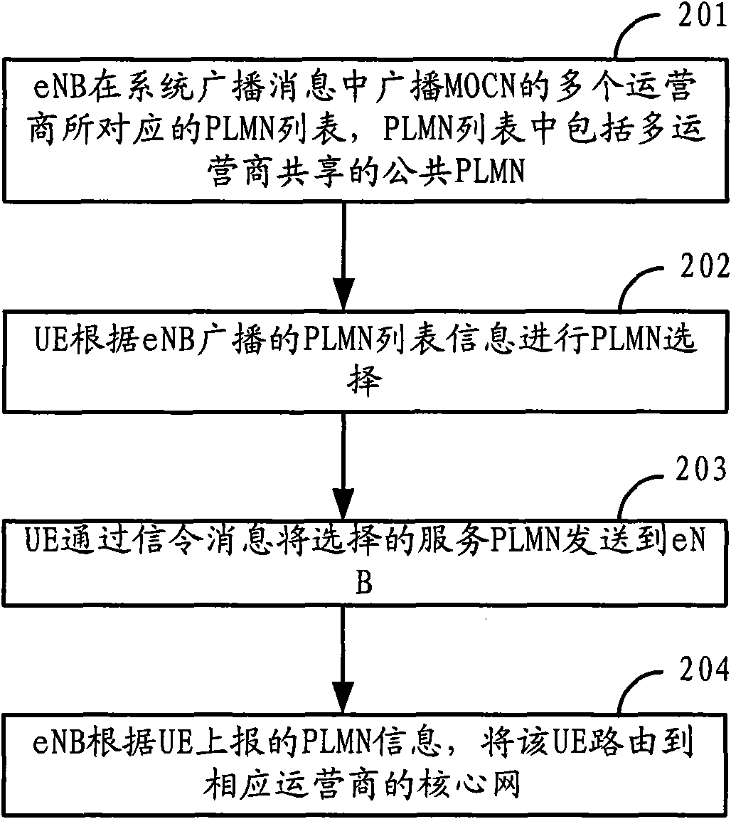
[0028] The following combined application scenario diagram figure 1 and method flow diagram figure 2 , to describe the embodiment of the present invention. as attached figure 1 As shown, PLMNA represents the network of operator A, PLMNB represents the network of operator B, PLMNC represents the RAN shared network jointly constructed by operator A and operator B, and PLMNC is a public PLMN shared by multiple operators.
[0029] The method comprises the steps of:
[0030] Step 201: In the MOCN cell, the base station eNB broadcasts the PLMN list information corresponding to multiple operators of the MOCN in a system broadcast message, wherein the PLMN list includes a public PLMN shared by multiple operators;
[0031] Taking the cell where the UE accesses the LTE shared core network as an example, the eNB broadcasts three PLMN information at the same time. The arrangement of the PLMN information in the broadcast information can have a default priority from high to low, and the...
Embodiment 3
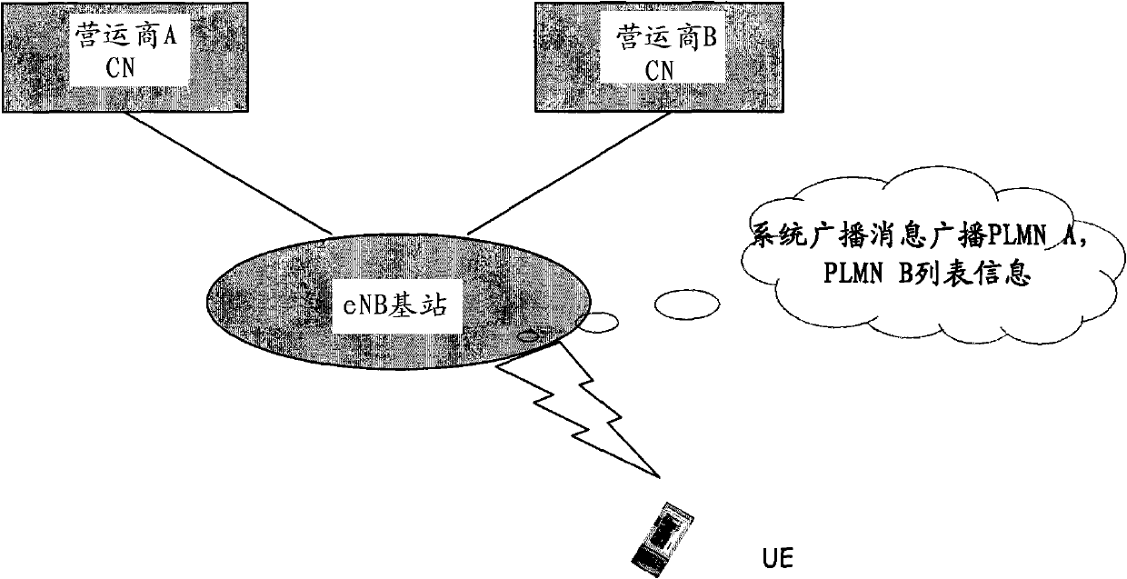
[0056] In the actual shared network construction, multiple operators may build or operate in different regions, so in the area that a certain operator is responsible for, the operator has the priority to ensure its interests. The embodiment of the present invention provides a technical solution to solve this problem, and the following will be combined with the schematic diagram of the application scene image 3 and a flow chart of the method Figure 4 , to describe the embodiment of the present invention.
[0057] Schematic Diagram of Application Scenarios image 3 In , PLMNA represents the network of operator A, and PLMNB represents the network of operator B, and the MOCN area is the operating area that operator A is responsible for.
[0058] The embodiment of the present invention specifically includes the following steps:
[0059] Step 401: In the MOCN cell, the base station eNB simultaneously broadcasts the PLMN list information corresponding to multiple operators of th...
PUM
 Abstract
Description
Claims
Application Information
 - R&D
- Intellectual Property
- Life Sciences
- Materials
- Tech Scout
- Unparalleled Data Quality
- Higher Quality Content
- 60% Fewer Hallucinations
Browse by: Latest US Patents, China's latest patents, Technical Efficacy Thesaurus, Application Domain, Technology Topic, Popular Technical Reports.
© 2025 PatSnap. All rights reserved.Legal|Privacy policy|Modern Slavery Act Transparency Statement|Sitemap|About US| Contact US: help@patsnap.com


