Mechanism with side mold core and sliding seat installed in fixing die and angle pin installed in moving die

A side core and mold mechanism technology, applied in the field of metal die-casting molds and plastic injection molds, can solve problems such as difficult processing and complex mold structures

Inactive Publication Date: 2011-04-27
牟维军
View PDF0 Cites 8 Cited by
  • Summary
  • Abstract
  • Description
  • Claims
  • Application Information

AI Technical Summary

Problems solved by technology

However, in actual production, some products are special, and it is difficult to meet the above principles. Therefore, according to the particularity of the product, the principle of parting surface selection must be violated. Therefore, the mold structure is complicated and the processing is difficult. It is not suitable for some special products. Combining with years of design experience in the mold industry, I now promote the following mold mechanism to the industry

Method used


Image

  • Mechanism with side mold core and sliding seat installed in fixing die and angle pin installed in moving die

Examples


Embodiment Construction

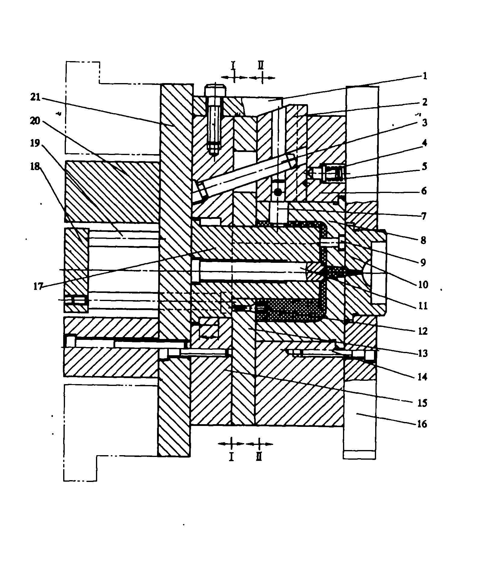
[0011] The figure shows a mold mechanism in which the side core and sliding seat are installed on the fixed mold, and the inclined guide post is installed on the movable mold. When opening the mold, the mold is divided by the I-I parting surface. Before the parting distance reaches the H value, the active force of the movable template 15 on the main core 17 is not large, so the main core remains motionless, and the oblique pin pulls the sliding seat 2 to extract the side core 7 . When the movable template 15 touches the shoulder surface of the main mold core 17, the main mold core starts to retreat together with the movable mold. Because the product has a strong wrapping force on the main mold core 17, the product presses the pusher plate 13 and retreats together, so II -II parting surface type. When releasing, the connecting push rod 19 promotes the push piece plate 13, because the insert positioning screw rod 12 is in the push piece plate 13 holes, so the product needs to b...


PUM


Abstract

The invention relates to a die mechanism with a side mold core and a sliding seat installed in a fixing die and an angle pin installed in a moving die. The die mechanism comprises the parts, such as a bolt, a guide post, a mold core, a mold insert, a supporting plate, a supporting block, a connecting push rod, a push plate, a main mold core, a fixing mold seat plate, a moving die plate, a locating screw rod, a mold core, a sprue bush, a concave die, the side mold core, a fixing die fixing plate, a spring locating pin, the angle pin, the sliding seat, a locking wedge, and the like showing the connecting mode in attached drawings of the specification). Two horizontal parting surfaces are designed for a die, wherein one parting surface is used for withdrawing a side loose core, and the other parting surface is used for taking out a product. The side mold core and the sliding seat are installed in the direction of the fixing die, and the angle pin is installed on one side of the moving die. Meanwhile, the main mold core is designed for the die to do delay action, thereby ensuring that the product is separated without remaining in the fixing die.

Description

technical field [0001] The invention relates to a metal die-casting mold and a plastic injection mold, and is a mold mechanism in which a side core and a sliding seat are designed on a fixed mold, and inclined guide columns are designed on a movable mold. Background technique [0002] In the field of mold design, in terms of product classification, usually, the principle of product classification is: A product is most likely to stay on the side of the movable mold after classification, and B, the big end and long end core pull are designed to open and close the mold as much as possible. Die direction. For products with a large projection area, try to design the side with the large projection area in the direction of mold opening and closing. D For products with side core pulling, the side core pulling should be designed on the side of the moving mold as much as possible to achieve the purpose of simplifying the mold mechanism. However, in actual production, some products a...

Claims


Application Information

Patent Timeline
Patent Type & Authority Applications(China)
IPC IPC(8): B22D17/22B29C45/26
Inventor 牟维军
Owner 牟维军
Why Eureka
Try Eureka