Manufacturing method of thin-wall variable-curvature hollow blade
A hollow blade and manufacturing method technology, applied in the field of manufacturing, can solve problems such as uneven accumulation of cladding layer wall thickness
Inactive Publication Date: 2011-04-27
XI AN JIAOTONG UNIV +1
View PDF6 Cites 23 Cited by
- Summary
- Abstract
- Description
- Claims
- Application Information
AI Technical Summary
Problems solved by technology
[0004] The invention aims to solve the problem of uneven accumulation of cladding layer wall thickness in the process of laser metal forming thin-walled blades, and provides a method for adjusting the laser power according to the radius of curvature of the hollow blade contour to control the temperature of the cladding layer molten pool, and then Improving the Wall Thickness Accuracy of Laser Metal Forming Thin-walled Blades
Method used
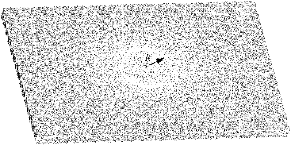
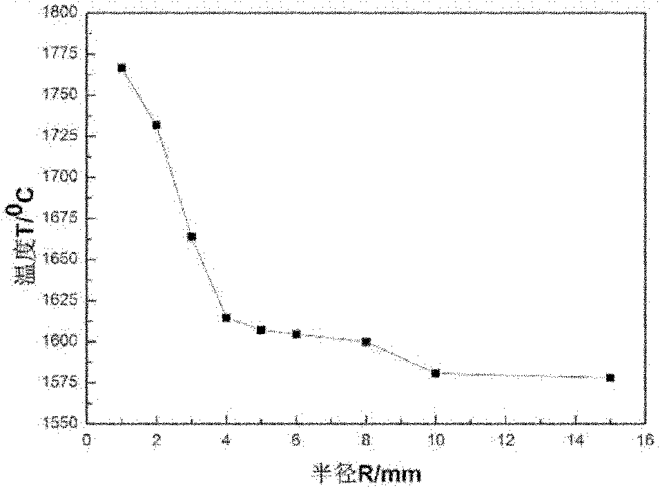
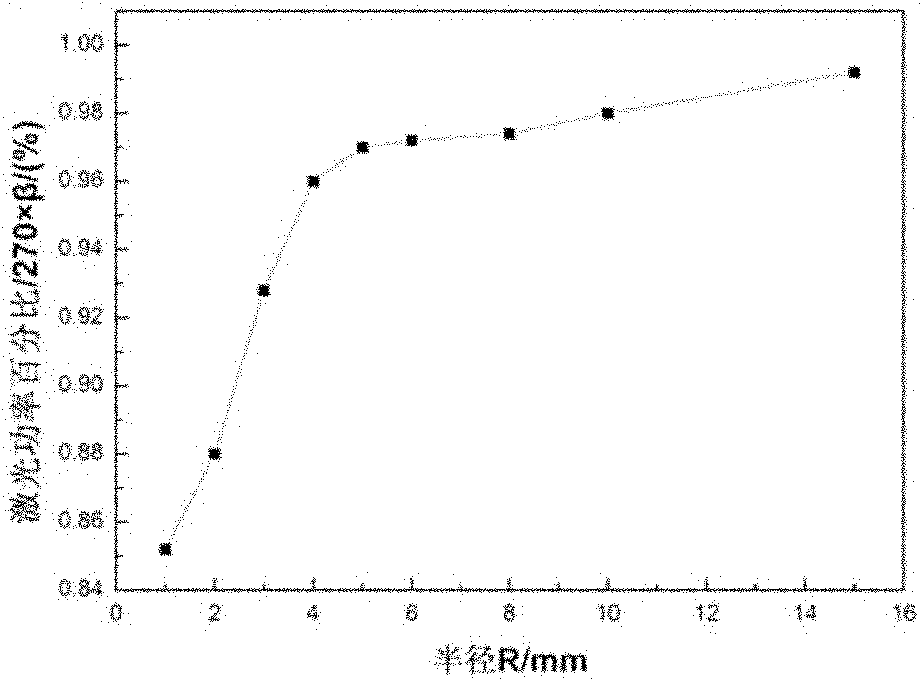
View moreImage
Smart ImageViewing Examples
Examples
Embodiment example
[0035] Laser metal direct forming of thin-walled variable-curvature hollow blades
Login to View More PUM
 Abstract
The invention discloses a manufacturing method of a thin-wall variable-curvature hollow blade. The method is characterized by being a method for manufacturing the thin-wall variable-curvature hollow blade according to a profile curvature radius and layer number adjusting laser power. The rule of the influence of profile curvature radius change of the blade on a molten pool temperature field is found so as to find a molten pool temperature field distribution rule corresponding to different curvature radiuses. A method for stabilizing the temperature of a molten pool by changing laser power is provided so as to obtain the rule of the change of laser power along with the curvature radius. The change rule is combined with power change along with layer number and laser power on any layer and any curvature are found, so that a thin-wall blade sample with uniform wall thickness can be molded according to the change rule at a stable molten pool temperature.
Description
technical field [0001] The invention relates to the manufacturing fields of laser surface cladding and surface repair of vulnerable parts, in particular to a manufacturing method of complex thin-walled parts and solid parts with large curvature radius changes in laser metal direct forming, and in particular to a method for adjusting laser beams according to contour curvature radius Method for manufacturing thin-walled hollow blades, Background technique [0002] Laser metal forming technology is an advanced manufacturing technology developed on the basis of laser cladding combined with rapid prototyping technology. Based on the "discrete-stack" forming principle, first establish the 3D model of the target part, then divide the 3D model slice into a series of 2D planes, plan a reasonable laser scanning path according to the 2D plane profile information, and then transform it into CNC The operation instructions of the workbench finally realize the direct accumulation and form...
Claims
Login to View More Application Information
Patent Timeline
 Patent Type & Authority Applications(China)
IPC IPC(8): B22F3/105C23C24/10B23K26/34B23K26/02B23K26/042
Inventor 张安峰李涤尘朱刚贤路桥潘同治强卢秉恒
Owner XI AN JIAOTONG UNIV
Features
- R&D
- Intellectual Property
- Life Sciences
- Materials
- Tech Scout
- Unparalleled Data Quality
- Higher Quality Content
- 60% Fewer Hallucinations
Learn More Browse by: Latest US Patents, China's latest patents, Technical Efficacy Thesaurus, Application Domain, Technology Topic, Popular Technical Reports.
© 2025 PatSnap. All rights reserved.Legal|Privacy policy|Modern Slavery Act Transparency Statement|Sitemap|About US| Contact US: help@patsnap.com


