
Arc welding method and arc welding system

An arc welding method and arc welding technology are applied to arc welding equipment, welding equipment, manufacturing tools, etc., and can solve problems such as deterioration of the appearance of the weld bead and occurrence of spatter

Active Publication Date: 2011-04-27
DAIHEN CORP
View PDF6 Cites 2 Cited by
  • Summary
  • Abstract
  • Description
  • Claims
  • Application Information

AI Technical Summary

Problems solved by technology

When the arc a reoccurs, spatter may occur, which may cause deterioration of the appearance of the scaly weld bead.

Method used


Image

  • Arc welding method and arc welding system
  • Arc welding method and arc welding system
  • Arc welding method and arc welding system

Examples


Embodiment Construction

[0093] Hereinafter, embodiments of the present invention will be specifically described with reference to the drawings.

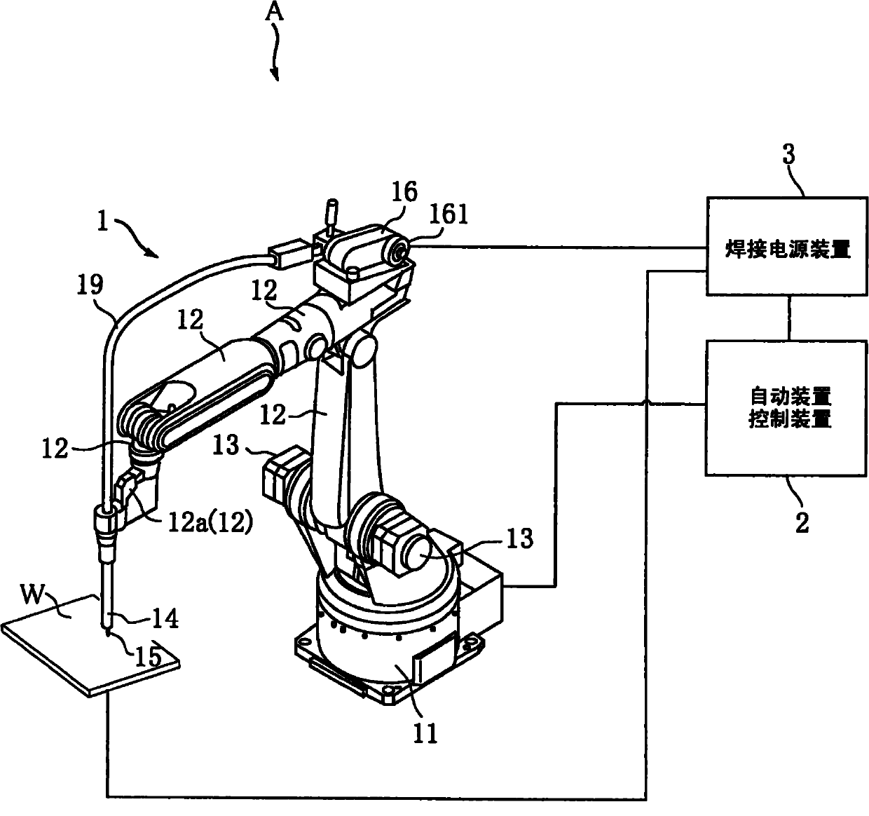
[0094] figure 1 It is a configuration diagram showing an example of the welding system according to the first embodiment of the present invention.

[0095] figure 1 The illustrated welding system A has a welding robot 1 , a robot control device 2 , and a welding power supply device 3 . The welding robot 1 automatically performs arc welding on the welding base material W, for example. The welding robot 1 has a base member 11 , a plurality of arms 12 , a plurality of motors 13 , a welding torch 14 , a welding wire feeder 16 , and a coil guide 19 .

[0096] The base member 11 is fixed at a suitable position such as the ground. Each arm 12 is connected to the base member 11 via a shaft.

[0097] The welding torch 14 is provided at the front end of the arm part 12 a provided at the front end of the welding robot 1 . The welding torch 14 guides a welding ...


PUM


Abstract

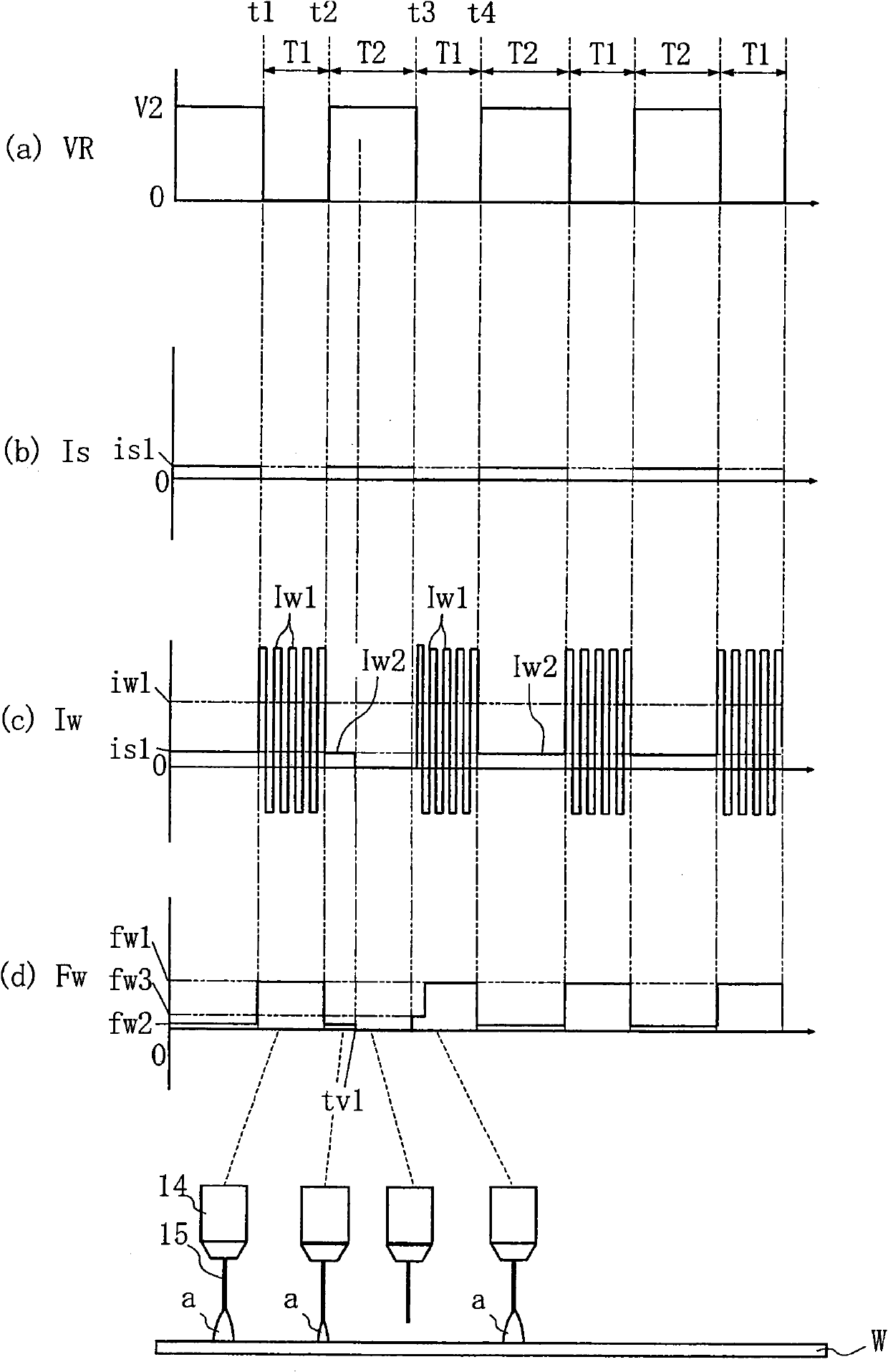
The invention provides an arc welding method, which enables better ripple welds to be formed. The arc welding method comprises a step 1, where a welding current Iw, of which the mean absolute value is current value iw1, running through between a welding wire (15) and welding base material generates arc a and transfers droplets; a step 2, where a welding current Iw, of which the mean absolute value, current value is1, is smaller than the current value iw1, generates arc (a). The step 1 and the step 2 are carried out repeatedly. The arc welding method also comprises a step to maintain the arc (a) in a quenched state during a moment tv1 to a moment t3, wherein the tv1 is the moment when the arc (a) is quenched at the step 2 and the t3 is the moment when the next step 1 starts. In such a structure, the arc (a) is maintained in a quenched state during moment tv1 to a moment t3 until no arc (a) is generated at the moment t3. Therefore, damage to the appearance of a weld due to arc (a) regenerated before the moment t3 can be avoided, thereby forming a better ripple weld.

Description

technical field [0001] The invention relates to an arc welding method and an arc welding system. Background technique [0002] Image 6 It is a figure which shows an example of the conventional welding system. The welding system 91 in this figure performs welding using so-called stitch pulse welding. The so-called joint pulse welding method is a welding method that can easily suppress the thermal influence on the base metal by controlling the heat input and cooling during welding. When this seam pulse welding method is used, compared with conventional sheet welding, the appearance of welding can be improved and the amount of welding deformation can be reduced (for example, refer to Patent Document 1). [0003] The manipulator 9M automatically performs arc welding on the workpiece 9W. The manipulator 9M is composed of an upper arm 93 , a lower arm 94 , and a wrist 95 , and a plurality of servo motors (not shown) for rotationally driving these. [0004] The arc welding torc...

Claims


Application Information

Patent Timeline
Patent Type & Authority Applications(China)
IPC IPC(8): B23K9/00B23K9/09B23K9/095
Inventor 广田周吾中川慎一郎高桥宪人藤井督士
Owner DAIHEN CORP
Learn More