Permanent magnet rotator and motor using the same

a permanent magnet rotator and permanent magnet technology, applied in the direction of magnetic circuit rotating parts, magnetic body, magnetic circuit shape/form/construction, etc., can solve the problems of increasing the vibration and noise of the motor, not necessarily giving high performance to the magnet, and increasing the power consumption of the motor, so as to reduce the power consumption and save resources

Active Publication Date: 2010-07-20
PANASONIC CORP
View PDF6 Cites 1 Cited by
  • Summary
  • Abstract
  • Description
  • Claims
  • Application Information

AI Technical Summary

Benefits of technology

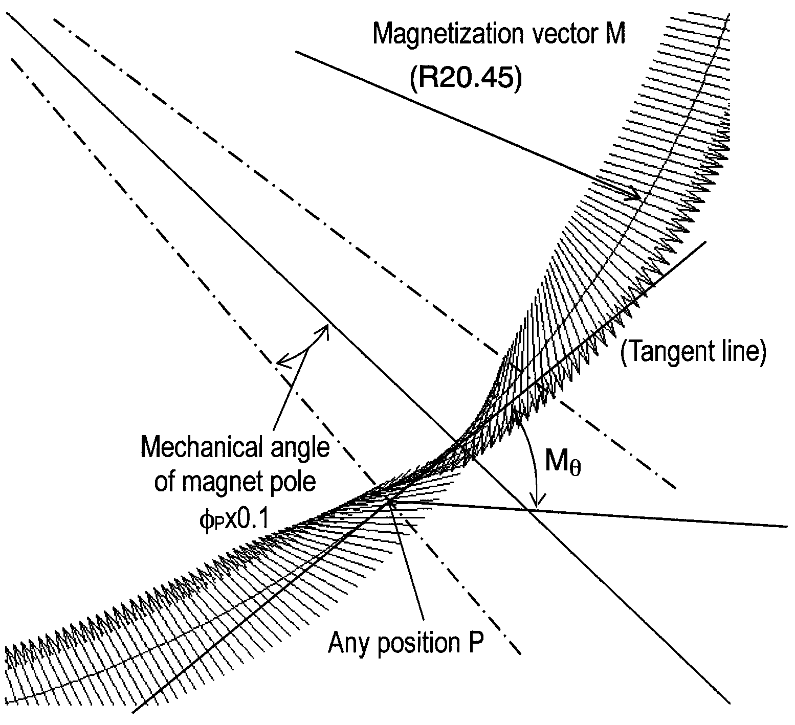
[0040]The present invention provides a continuous direction control for anisotropy with modification of magnetic poles so that direction (Mθ) of anisotropy with respect to a mechanical angle (θ) can have a distribution of 90×sin [φ{2π / (360 / p)}], thereby increasing torque density without increasing cogging torque of a motor, irrespective of anisotropic magnetic poles which has energy density about two times as high as energy density of isotropic magnet sinusoidally-magnetized with the energy density (BH) max≧80 kJ / m3.
[0041]Accordingly, the present invention is useful for reduction of power consumption, savings in resources, miniaturization and quiescence of permanent magnet type motors having their power capacity of less than about 50 W which are being widely used as various kinds of driving sources for home appliances, air conditioners, information devices, etc.

Problems solved by technology

The magnet's strong attractive and repulsive ability does not necessarily give high performance to the magnet depending on the kind of magnet.
The increase of cogging torque disturbs smooth rotation of the motor, which results in increase of vibration and noise of the motor, thereby causing a bad effect such as deterioration of rotation controllability.
Thus, when the thickness of magnetic poles 1, that is, direction (thickness) of magnetization M, becomes small, it is difficult to sufficiently reduce cogging torque through the thickness-deviation of magnetic poles 1.
Moreover, in general, it is difficult to treat the magnetic poles because of their fragile mechanical property.
As a result, the above-mentioned methods typically lower torque density by 10 to 15% due to the reduction of cogging torque.
However, for the Nd2Fe14B-based rare-earth sintered magnet having the thickness of 1.2 mm and the high energy density with residual magnetization (Mr) of 1 T, it is difficult to regularly and minutely arrange magnetic pole pieces having different directions of anisotropy and configure the magnetic poles with high dimensional precision.
Thus, it is very difficult to manufacture a multi-pole rotator provided with an integral multiple of magnetic poles or a radial airgap type magnet motor using the multi-pole rotator.
In addition, it may be guessed without difficulty that motors employing the above-mentioned Halbach Cylinder are uneconomical.
However, it is difficult to finely control the direction of magnetic flux (φ) of the cavity portion.
As described above, although the conventional techniques increase torque density of a motor with increase of energy density (BH) max, these techniques have the problem of deterioration of quiescence and controllability with increase of cogging torque.

Method used


Image

  • Permanent magnet rotator and motor using the same
  • Permanent magnet rotator and motor using the same
  • Permanent magnet rotator and motor using the same

Examples


embodiment

[0088]Hereinafter, according to an embodiment of the present invention, magnetic poles having continuously-controlled anisotropy, an 8-pole permanent magnet rotator, and a 8-pole / 12-slot permanent magnet type motor will be described in more detail. However, the present invention is not limited to this embodiment.

[0089]In this embodiment, material composition of a magnet includes anisotropic Sm2Fe17N3-based rare-earth magnet powders of 32.1 vol. % having energy density (BH) max=290 kJ / m3 and particle diameter of 3 to 5 μm, anisotropic Nd2Fe14B-based rare-earth magnet particles of 48.9 vol. % having energy density (BH) max=270 kJ / m3 and particle diameter of 38 to 150 μm, novolak epoxy oligomer of 6.2 vol. %, linear polyamide of 9.1 vol. %, 2-phenyl-4,5-dihydroxymethylimidazole of 1.8 vol. %, and a lubricant (pentaerytritol stearic acid triester) of 1.9 vol. %.

[0090]First, as shown in FIG. 5, magnetic pole 51 before modified with 50 MPa of a uniform oriented magnetic field Hex of 1.4 M...


PUM


Abstract

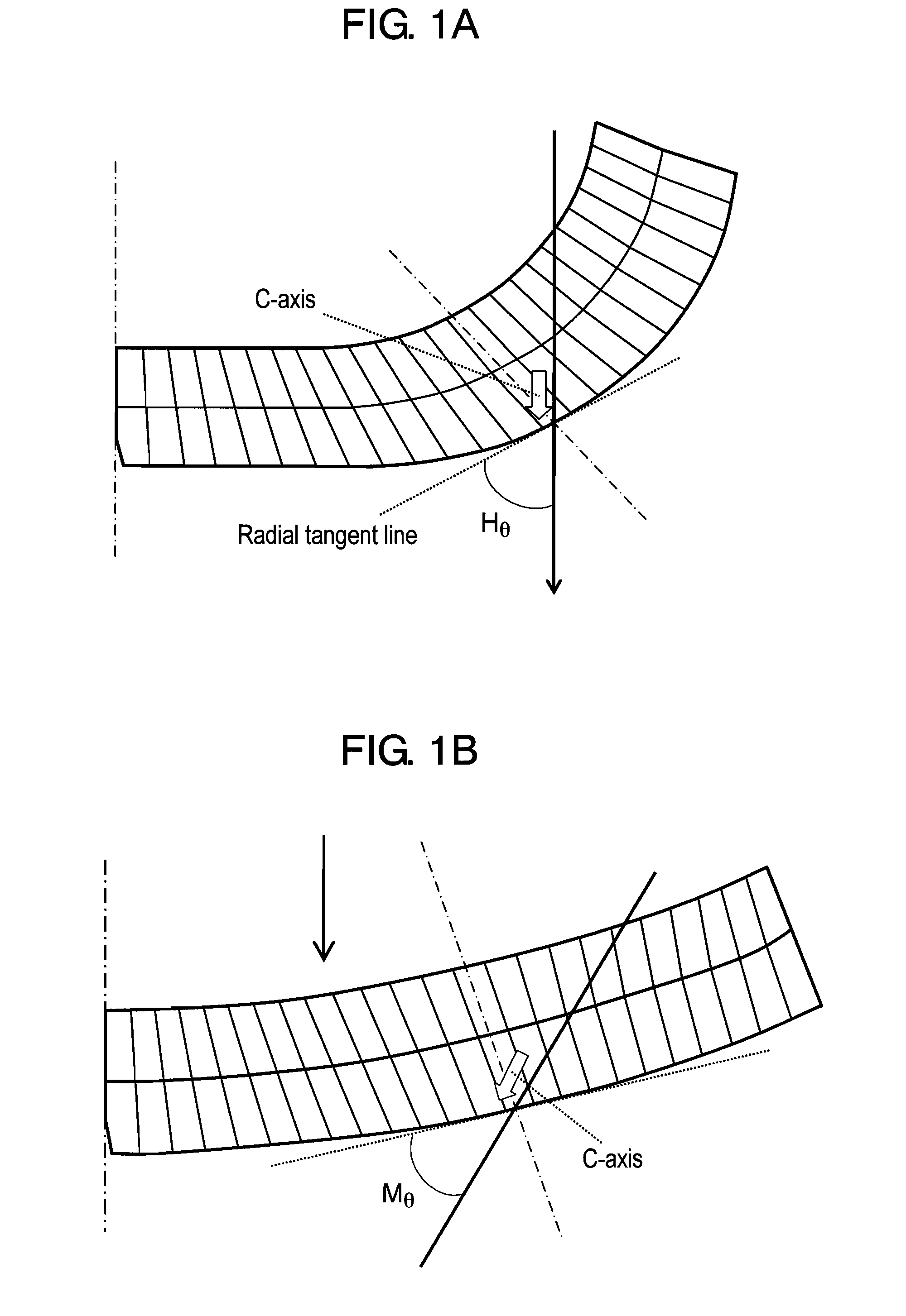
A motor generally has a contradictory relation between decrease of cogging torque and increase of torque density. To overcome this problem, continuous direction control is provided for anisotropy with modification of magnetic poles so that the average absolute value of differences between Mθ and 90×sin [φ{2π / (360 / p)}] is set to be 3° or less, where Mθ is a direction of anisotropy with respect to a radial tangent line of a magnetic pole plane, φ is a mechanical angle, and p is the number of pole pairs.

Description

TECHNICAL FIELD[0001]The present invention relates to a permanent magnet rotator which is capable of providing continuous direction control for anisotropy with modification of a magnetic pole so that direction Mθ of anisotropy with respect to a mechanical angle φ can have a distribution of 90×sin [({2π / (360 / p)}]. More particularly, the present invention relates to a permanent magnet rotator which is capable of providing continuous direction control for anisotropy for the purpose of reduction of power consumption, savings in resources, miniaturization and quiescence of permanent magnet type motors having their power capacity of less than about 50 W which are being widely used as various kinds of driving sources for home appliances, air conditioners, information devices, etc, and a motor using the same.BACKGROUND ART[0002]A motor may be referred to as a multi-function part for changing electric energy to mechanical energy by a combination of a shaft, a bearing, a stator, etc. made by ...

Claims


Application Information

Patent Timeline
Patent Type & Authority Patents(United States)
IPC IPC(8): H02K1/27H02K1/22
CPCH01F1/0578H01F1/059H02K1/27H02K15/03
Inventor YAMASHITA, FUMITOSHIMURAKAMI, HIROSHIOKADA, YUKIHIROKAWAMURA, KIYOMI
Owner PANASONIC CORP
Why Eureka
Try Eureka