Un-stacking method and stack bag detachment device

A technology for pallets and bags, applied in the field of destacking, stacking and unpacking devices, and can solve problems such as low operation efficiency, high labor intensity of workers, and inability to connect conveying systems.

Inactive Publication Date: 2011-04-27
CIMC ENRIC ENGINEERING TECHNOLOGY CO LTD
View PDF0 Cites 8 Cited by
  • Summary
  • Abstract
  • Description
  • Claims
  • Application Information

AI Technical Summary

Problems solved by technology

At present, the palletizer can quickly stack the packaging bags of specific specifications on the pallet according to certain rules, but the depalletizing process (reverse process of palletizing) required for warehouse delivery and loading has been completely completed by manpower for a long time

Method used


Image

  • Un-stacking method and stack bag detachment device
  • Un-stacking method and stack bag detachment device
  • Un-stacking method and stack bag detachment device

Examples


Embodiment 1

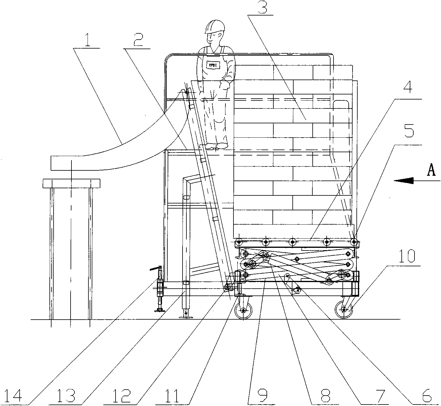
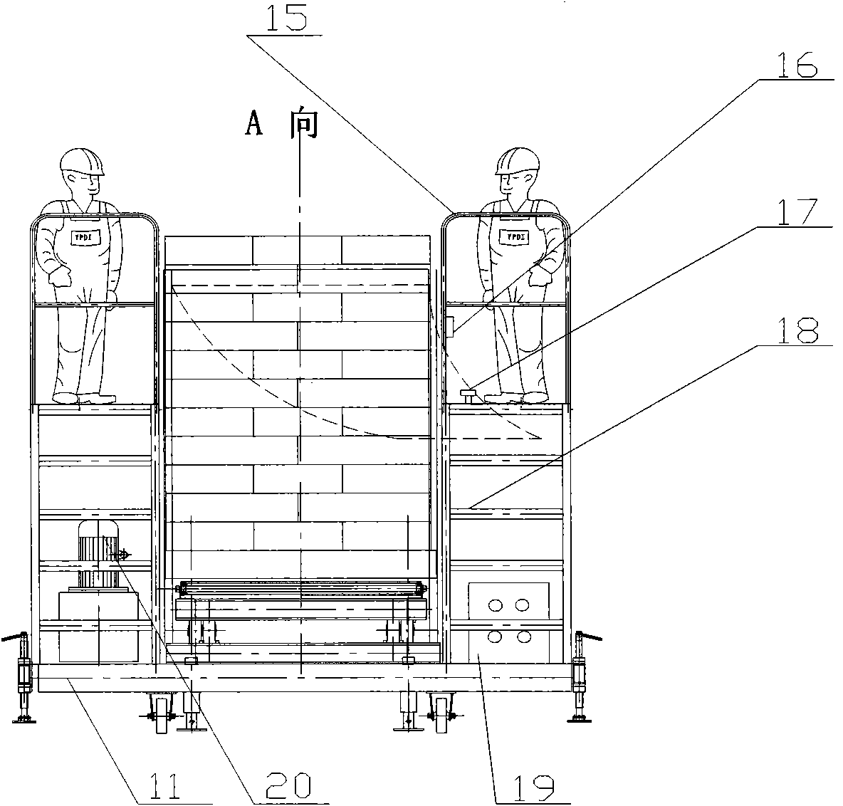
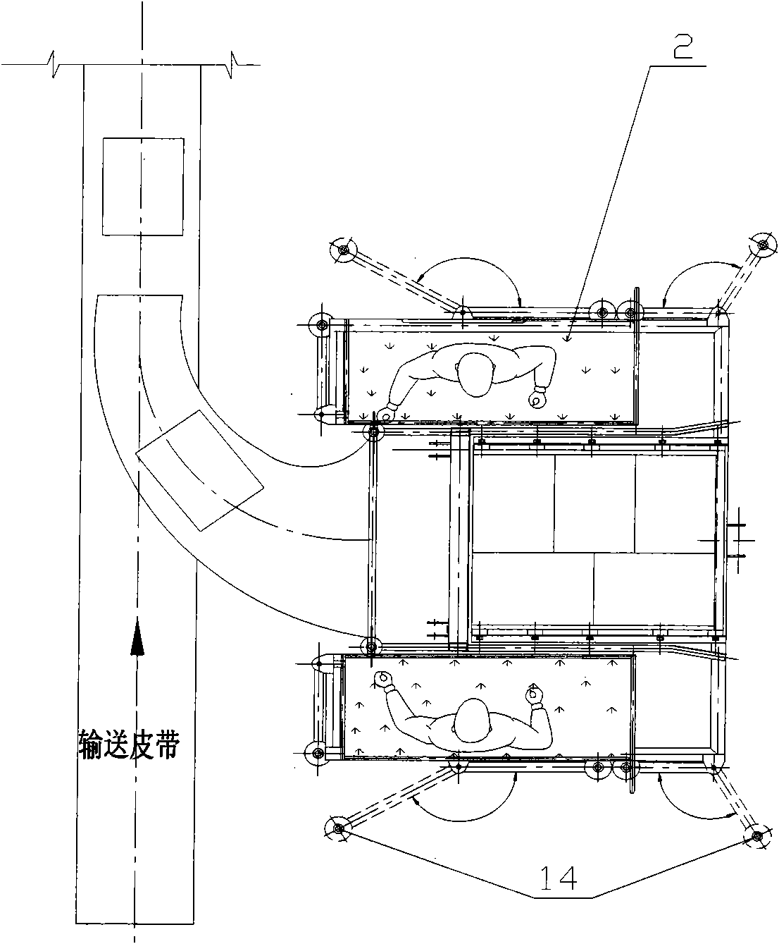
[0035] Such as Figure 1-Figure 6 Shown, underframe (11) is the chassis of whole machine in the pallet dismantling device of the present invention, is equipped with moving wheel (10), fixed support leg (13) and swing arm support leg (14) below it. The four moving wheels (10) are traveling mechanisms for moving the unpacking device; the two fixed legs (13) are located under the front two corners of the underframe (11), and the four swing arms (14) To increase the stability of the destacker, it can be rotated to an appropriate position according to the site conditions and then fixed.

[0036] On the bottom frame (11) are equipped with stacking warehouse (3), tiltable chassis (9), operating platform (2), climbing ladder (18), distribution box (19), hydraulic station (20) and chute (1 ).

[0037] The stacking bin (3) is surrounded by three side fixed bin walls, and one side opening is used for stacking. The two side walls of the stacker (3) are perpendicular to the bottom frame...

Embodiment 2

[0054] The stacking and unpacking device of the present invention may not be provided with a tilting mechanism, but the lifting frame of the lifting mechanism is directly mounted on the bottom frame, and one end of the lifting hydraulic cylinder is connected to the connecting rod B of the lifting frame, and the other end is connected to the connecting rod C or Attaches directly to the chassis. Thus, the tilting hydraulic cylinder, solenoid valve B and corresponding control switches can be omitted. All the other parts are the same as embodiment one.

Embodiment 3

[0056] The front wall of the stacker in the first embodiment above is fixed at an angle, which cannot be adjusted after being determined. The bottom of the front wall of the present embodiment is fixed on the tiltable chassis, and the inclination angle of the front wall is synchronized with the tiltable chassis, that is, the tiltable chassis drives the front wall to tilt together. The structure of other parts and the unstacking method are the same as in Embodiment 1.


PUM


Abstract

The invention relates to an un-stacking method and a stack bag detachment device. The un-stacking method comprises the following steps of: A, conveying a stack disc into a stack bin of the stack bag detachment device through a forklift; B, dragging bags on the stack disc into corresponding chutes by an operator, continually promoting the stack in the stack detachment operation, shifting out the bags layer by layer, and making the bags entering the chutes fall on a subsequent conveying device in turn; and C till the whole stack disc is completely detached, resetting the stack bag detachment device to prepare for detaching the next stack disc. The stack bag detachment device designed by the invention can assist the operator in quickly detaching the bags in the stack bag into single bags, and is convenient for supplying materials to a conveying system or loading. During stack detachment, the top bag of the stack is at an easy-carrying position all the time, and the bags can be moved into the chutes along the dragging of the operator. The device for finishing the stack detachment operation can save manpower, greatly reduce the labor intensity of the operator, and remarkably improve the speed and efficiency of stack detachment.

Description

1. Technical field [0001] The invention relates to a depalletizing method and a depalletizing device suitable for the depalletizing method, which can assist the operator to quickly dismantle the bags in the pallet into single packs, and supply materials or load them to the conveying system, It belongs to the field of transportation machinery. 2. Background technology [0002] Now, the operation method of packing powder and granular materials in bags and stacking them on pallets for convenient storage and transportation has been widely used in various industries such as chemical industry, grain, medicine, food, building materials, etc. Two important links that are indispensable in the process of similar warehousing and transportation operations. At present, the palletizer can quickly stack the packaging bags of specific specifications on the pallet according to certain rules, but the depalletizing process (reverse process of palletizing) required for warehouse delivery and l...

Claims


Application Information

Patent Timeline
IPC IPC(8): B65G59/02B66F7/08
Inventor 应捷成杨汉卿许炎夏
Owner CIMC ENRIC ENGINEERING TECHNOLOGY CO LTD
Why Eureka
Try Eureka