
Self-circulation anaerobic reactor

An anaerobic reactor and container technology, applied in anaerobic digestion treatment and other directions, can solve problems such as unfavorable gas mixing with influent water, inability to generate internal circulation, and reactor flocculation.

Inactive Publication Date: 2011-04-27
原保群
View PDF0 Cites 3 Cited by
  • Summary
  • Abstract
  • Description
  • Claims
  • Application Information

AI Technical Summary

Problems solved by technology

[0002] The commonly used internal circulation reactor is to add a set of gas collection hoods in the middle of the reactor. The gas collection hoods can use the density difference between the gas-liquid mixture and the liquid formed by the gas generated by the material in the reactor to separate the gas. The liquid mixture is raised above the liquid level in the reactor, and after the gas-liquid separation, the part of the liquid is returned to the bottom of the reactor by using the displacement difference of the liquid to form an internal circulation; however, the initial gas production of this reactor The starting speed is slow, so internal circulation cannot be generated. In addition, the power of the gas produced by this reactor can only be used once, so the flocculation in the reactor is insufficient, which is unfavorable for the mixing of gas and water.

Method used


Image

  • Self-circulation anaerobic reactor
  • Self-circulation anaerobic reactor
  • Self-circulation anaerobic reactor

Examples


Embodiment 1

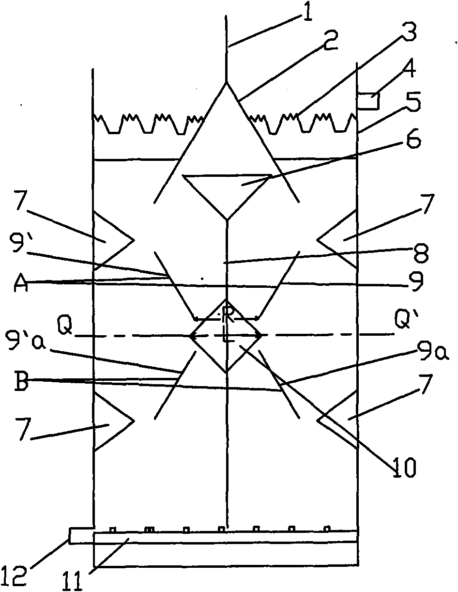
[0014] Embodiment 1: This self-circulating anaerobic reactor comprises a container 5, a water inlet pipe 12 communicating with the bottom of the container 5, a water distribution system 11 located at the bottom of the container 5 and connected with the water inlet pipe 12, and an overflow is provided on the top of the container 5. Flow weir 3, water outlet pipe 4 and a gas collection hood 2, the gas collection hood 2 is connected with the gas outlet pipe 1, the gas collection hood 2 is composed of two boards, the tops of the two boards intersect, and the angle between them is 45° There is a reflux funnel 6 and two layers of baffles on the bottom of the gas collection hood 2, and each layer of baffles has two plates that are installed obliquely in the container 5 but do not intersect. The vertical line in the middle is symmetrical; in this embodiment, the first layer of baffles A is composed of a plate 9 and a plate 9', and the plate 9 and the plate 9' are installed obliquely in...

Embodiment 2

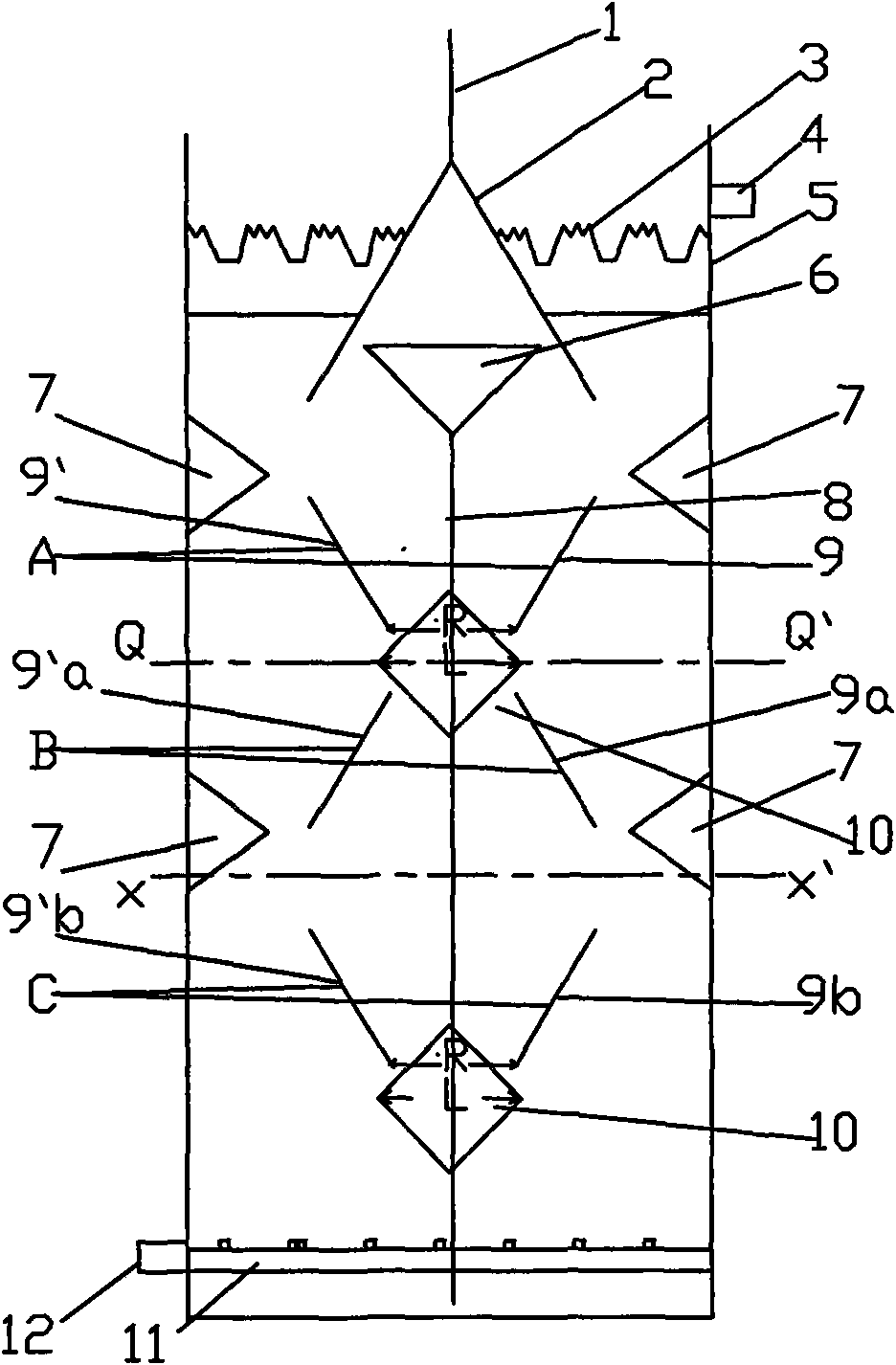
[0015] Embodiment 2: There are three layers of baffles on the lower side of the gas collecting hood 2 in this embodiment, the third layer of baffles C is made up of plate 9b and plate 9'b, the third layer of baffles C is connected with the second layer of baffles The baffle B is symmetrical with the horizontal line XX' in the middle of them, and the plate 9b and the plate 9'b in the third baffle C become an inverted "eight" shape; There is a shunt 10 . Other structures are the same as in Embodiment 1. The return pipe 8 communicated with the return funnel 6 passes through the gap in the middle of the three-layer baffle, and its outlet is located at the bottom of the container 5 . In addition to selecting 2-3 layers of baffles for use in the bottom of the gas collecting hood 2, 4 or 5 layers of baffles can also be selected according to the depth of the container in the self-circulating anaerobic reactor. If it is 4 layers of baffles, then the fourth layer of baffles and the th...

Embodiment 3

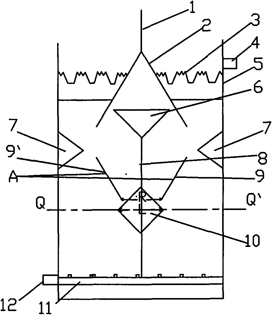
[0016] Embodiment 3: a gas collection hood 2 is arranged in the present embodiment, and a return funnel 6 and a deck of baffles are arranged below the gas collection hood 2. This baffle is made up of a plate 9 and a plate 9', and the plate 9 and The plates 9' are installed obliquely in the container 5, but these two plates do not intersect, and the angle formed by their extension lines is 45 °, and the plates 9 and 9' are symmetrical with the vertical line in the middle of them; and, the two plates The horizontal distance between the plates is closer to the end of the gas collecting hood than the end of the long horizontal distance between the two plates, forming an inverted "eight" shape; Distributor plate 7 is placed on the container inner wall, and the structure and installation position of water inlet pipe 12, water distribution system 11, overflow weir 3, water outlet pipe 4, gas collecting hood 2, return flow funnel 6 and return pipe among the present embodiment are all c...


PUM


Abstract

The invention discloses a self-circulation anaerobic reactor. The self-circulation anaerobic reactor comprises a container, a water inlet pipe and a water distribution system, wherein the water inlet pipe is communicated with the lower part of the container; the water distribution system is positioned on the lower part of the container and communicated with the water inlet pipe; a baffle plate, a backflow funnel and a return pipe which is communicated with the backflow funnel are arranged in the container; the upper part of the container is provided with a gas collecting hood, an overflow weir and a water outlet pipe; the gas collecting hood is communicated with the gas outlet pipe; the wall of the container is provided with a splitter plate; the upper part of the container is at least provided with one gas collecting hood which is communicated with the gas outlet pipe; the backflow funnel is positioned on the lower edge of the gas collecting hood; the lower edge of each gas collecting hood is at least provided with one layer of baffle plate; each layer of baffle plate on the lower edge of each gas collecting hood at least consists of two plates which are slantwise arranged in the container but are not crossed; the outlet of the return pipe which is connected with the backflow funnel is positioned on the lower part in the container; thus, the reactor contributes to mixing of inlet water and gas, has high starting speed and produces backflow and middle turbulence at the preliminary stage of starting.

Description

technical field [0001] The invention belongs to sewage treatment equipment. In particular it relates to internal loop reactors. Background technique [0002] The commonly used internal circulation reactor is to add a group of gas collection hoods in the middle of the reactor. The gas collection hoods can use the density difference between the gas-liquid mixture and the liquid formed by the gas generated by the material in the reactor to separate the gas. The liquid mixture is lifted above the liquid level in the reactor, and after the gas-liquid separation, the part of the liquid is returned to the bottom of the reactor by using the displacement difference of the liquid to form an internal circulation; however, the initial gas production of this reactor The starting speed is slow, so internal circulation cannot be generated. In addition, the power of the gas produced by this reactor can only be used once, so the flocculation in the reactor is insufficient, which is unfavora...

Claims


Application Information

Patent Timeline
Patent Type & Authority Applications(China)
IPC IPC(8): C02F3/28
Inventor 原保群
Owner 原保群
Learn More