Supercharge Your Innovation With Domain-Expert AI Agents!

Cab sliding device of engineering machinery

A technology of construction machinery and sliding devices, which is applied to earth movers/shovels, construction, etc., can solve the problems of difficulty in obtaining flatness, excessive or insufficient bending degree, and labor-intensive assembly, so as to achieve easy disassembly and easy to ensure Effect

Active Publication Date: 2011-04-27
NIHON KENKI CO LTD
View PDF3 Cites 0 Cited by
  • Summary
  • Abstract
  • Description
  • Claims
  • Application Information

AI Technical Summary

Problems solved by technology

[0004] However, in the sliding device of the above-mentioned conventional cab, in order to install the upper bed on the lower bed, the upper bed must be inserted from the front side of the lower bed and slide it. it takes effort
In addition, in order to replace the slide plate installed inside the U-shaped guide part, the upper bed must be pulled out from the lower bed and disassembled, and maintenance work is also labor-intensive.
[0005] In addition, in order to support the upper bed, a plurality of slide plates (for example, 5 each on the left and right sides), a total of, for example, 20 slide plates are respectively arranged on the upper and lower sides of the guide parts on the left and right sides of the lower bed. A plurality of sliders are also provided on the sides of the left and right sliding parts of the upper bed. In addition, height adjustment mechanisms such as spacers interposed between the sliders and the guide part or the slider are required, so the number of parts and the number of installation man-hours are also limited. more, higher cost
[0006] In addition, the guide part provided on the lower bed is formed by bending a flat plate into a U-shape, which tends to cause excessive or insufficient bending, and it is difficult to obtain flatness.
Moreover, even if the flatness is desired, it is difficult to obtain the flatness because it is difficult to make the tool enter the inside of the U-shaped guide portion for processing.
Therefore, in order to allow the upper bed to slide smoothly with respect to the lower bed, it is necessary to perform complex and many-hour adjustment work such as height adjustment of a plurality of sliding plates using spacers, etc., so the adjustment work requires labor and time.

Method used


Image

  • Cab sliding device of engineering machinery
  • Cab sliding device of engineering machinery
  • Cab sliding device of engineering machinery

Examples


Embodiment Construction

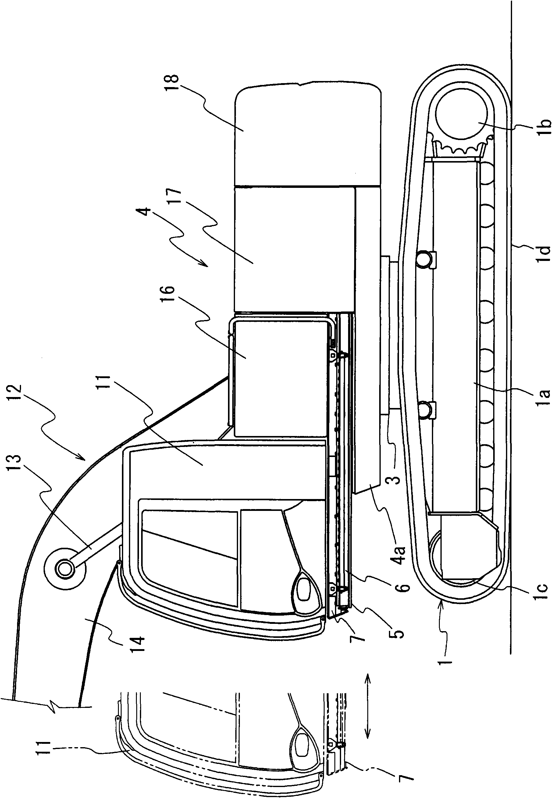
[0092] figure 1 It is a side view showing an example of a construction machine to which the present invention is applied. Attached body symbol 1 represents the undercarriage body, and the structure of this undercarriage body 1 is, has side frame 1a on the left and right side of the undercarriage body frame that swivel device 3 is arranged on the upper part, is installed in the rear portion of this side frame 1a by traveling motor. (not shown) driving wheel 1b driven, driven wheel 1c is installed on the front portion of side frame 1a, and crawler belt 1d is hung on driving wheel 1b and driven wheel 1c. The upper rotating body 4 is rotatably arranged on the running body frame through the rotating device 3 .

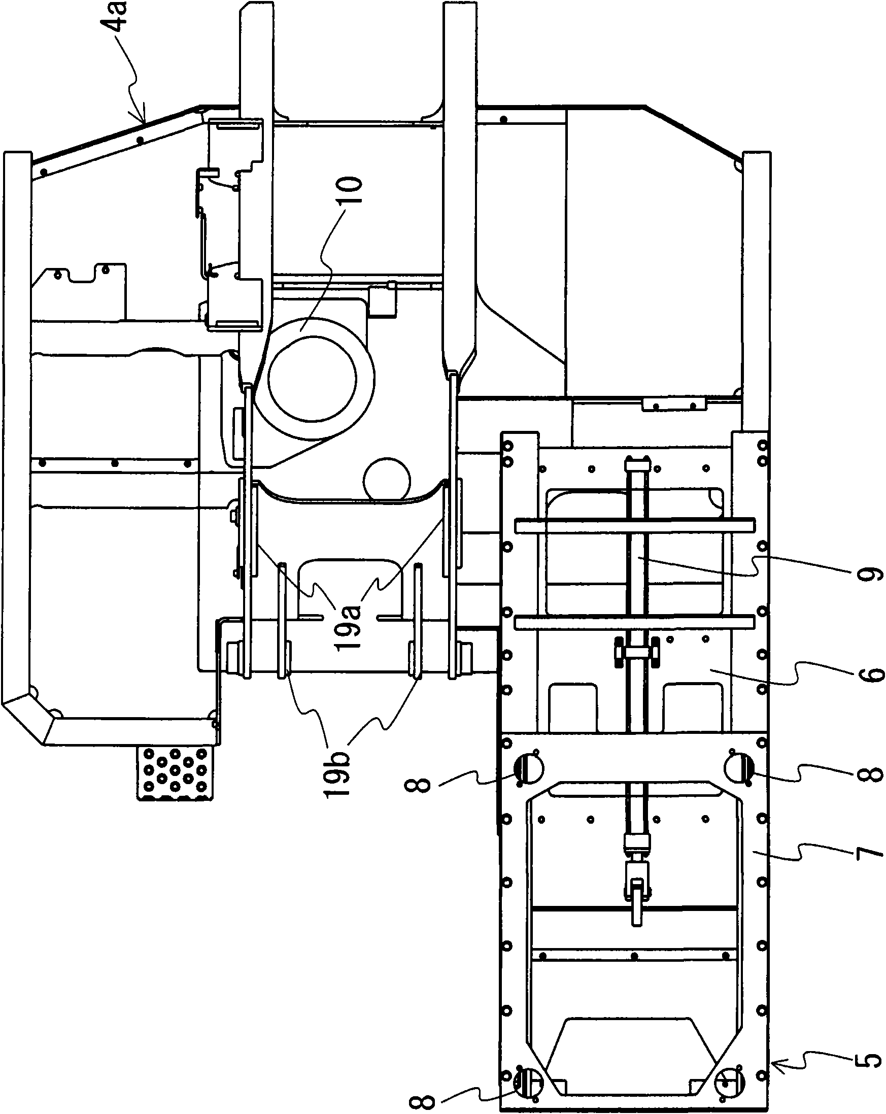
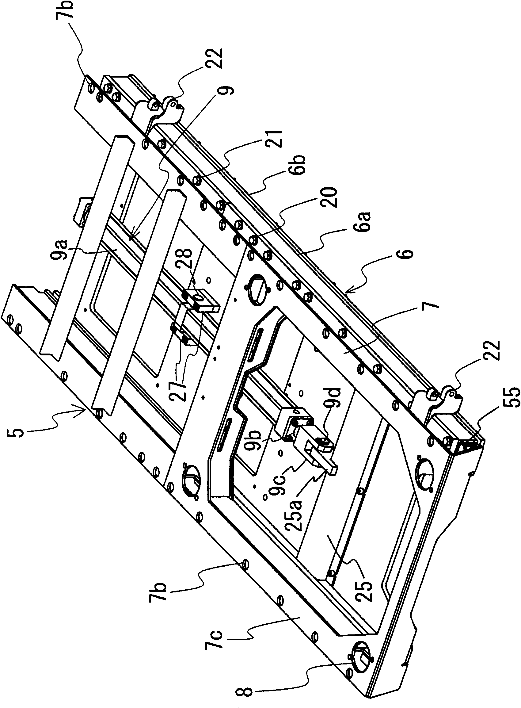
[0093] Such as figure 2 As shown in the plan view of , the revolving frame 4a constituting the upper revolving body 4 is provided with a bed 5 at the front of one side (the left side in the illustrated example). And, this bed 5 is made of the lower bed 6 fixed on the ro...


PUM


Abstract

The present invention provides a cab sliding device of engineering machinery, which can be easily assembled and detached in manufacturing and maintenance. The cab sliding device of the engineering machinery comprises the following components: a lower bed (6) which is equipped to a rotation frame of an upper rotation member, and an upper frame (7) which is equipped on the lower bed (6) with a movable mode in a front-and-back direction and carries the cab. A guiding part (6a) which is equipped on the lower bed (6) becomes a separated structure which is composed of an upper component (31) and a lower component (30). The upper component (31) and the lower component (30) are detachably combined through bolts (20,21) for forming a guiding part (6a) with a U-shaped cross section. Sliding parts (7a) which are equipped to the left side and the right side of the upper bed (7) are inserted into the guiding part (6a) through a slidable mode. At a state that upper component (31) is removed from the lower component (30), the sliding parts (7a) of the upper bed (7) can be inserted into the lower component (30) of the lower bed (6).

Description

technical field [0001] The invention relates to a device for sliding the cab of a construction machine forward and backward. technical background [0002] In construction machines, there is a device for sliding a cab back and forth in order to secure a field of vision during excavation work and the like. Conventionally, as a device for sliding the cab, for example, a structure described in Patent Document 1 has been employed. This conventional sliding device has the following structure: a guide part bent into a U-shaped cross-sectional shape is provided on the left and right sides of the lower bed as a fixed side frame, and the upper bed is inserted into the inner side of the guide part. The sliding part of the movable sliding frame with a U-shaped cross-sectional shape provided on both sides of the sliding part, a slide plate is interposed between the sliding part and the guiding part so that the sliding part can move relative to the guiding part. [0003] Patent Document...

Claims


Application Information

Patent Timeline
IPC IPC(8): E02F9/16
Inventor 江川秀二稻元昭多田茂也前原裕二
Owner NIHON KENKI CO LTD
Features
  • R&D
  • Intellectual Property
  • Life Sciences
  • Materials
  • Tech Scout
  • Unparalleled Data Quality
  • Higher Quality Content
  • 60% Fewer Hallucinations
Learn More