Gas lift method of combined ball plug for drainage and gas production of oil and gas well

A combined, ball-plug technology, applied in the production of fluids, earth-moving, wellbore/well components, etc., can solve the problems of limited running depth, poor economy, poor adaptability, and low system reliability, and achieve the structural principle. Simple, reliable results

Inactive Publication Date: 2011-04-27
CHINA UNIV OF PETROLEUM (BEIJING)
View PDF2 Cites 19 Cited by
  • Summary
  • Abstract
  • Description
  • Claims
  • Application Information

AI Technical Summary

Problems solved by technology

The system efficiency of the liquid drainage gas production well adopting the above-mentioned ball plug gas lift method is low, the formation energy cannot be fully utilized, the running depth is limited, and the reli...

Method used


Image

  • Gas lift method of combined ball plug for drainage and gas production of oil and gas well
  • Gas lift method of combined ball plug for drainage and gas production of oil and gas well

Examples


example 1

[0015] Bottomhole fluid accumulation occurs at the bottom of the gas well. Assuming that the main components of the liquid are water and oil, the density of the liquid is 800kg / m 3 , the acceleration due to gravity is 10m 2 / s, the rated working pressure of the ground compressor is 35Mpa, and the energy consumed by the damping force accounts for 20% of the output power. The specified rated working pressure is the maximum pressure required for the system to start. Theoretically the maximum descent depth is:

[0016] h 1 = P n x η / ρg =35×10 6 ×0.8 / 800 / 10=3500(m)

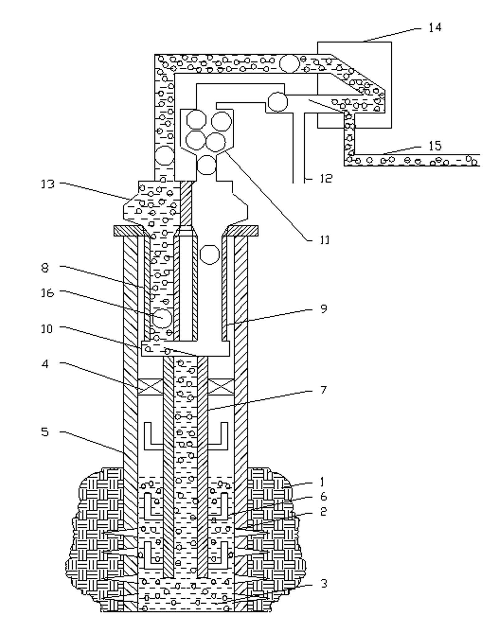
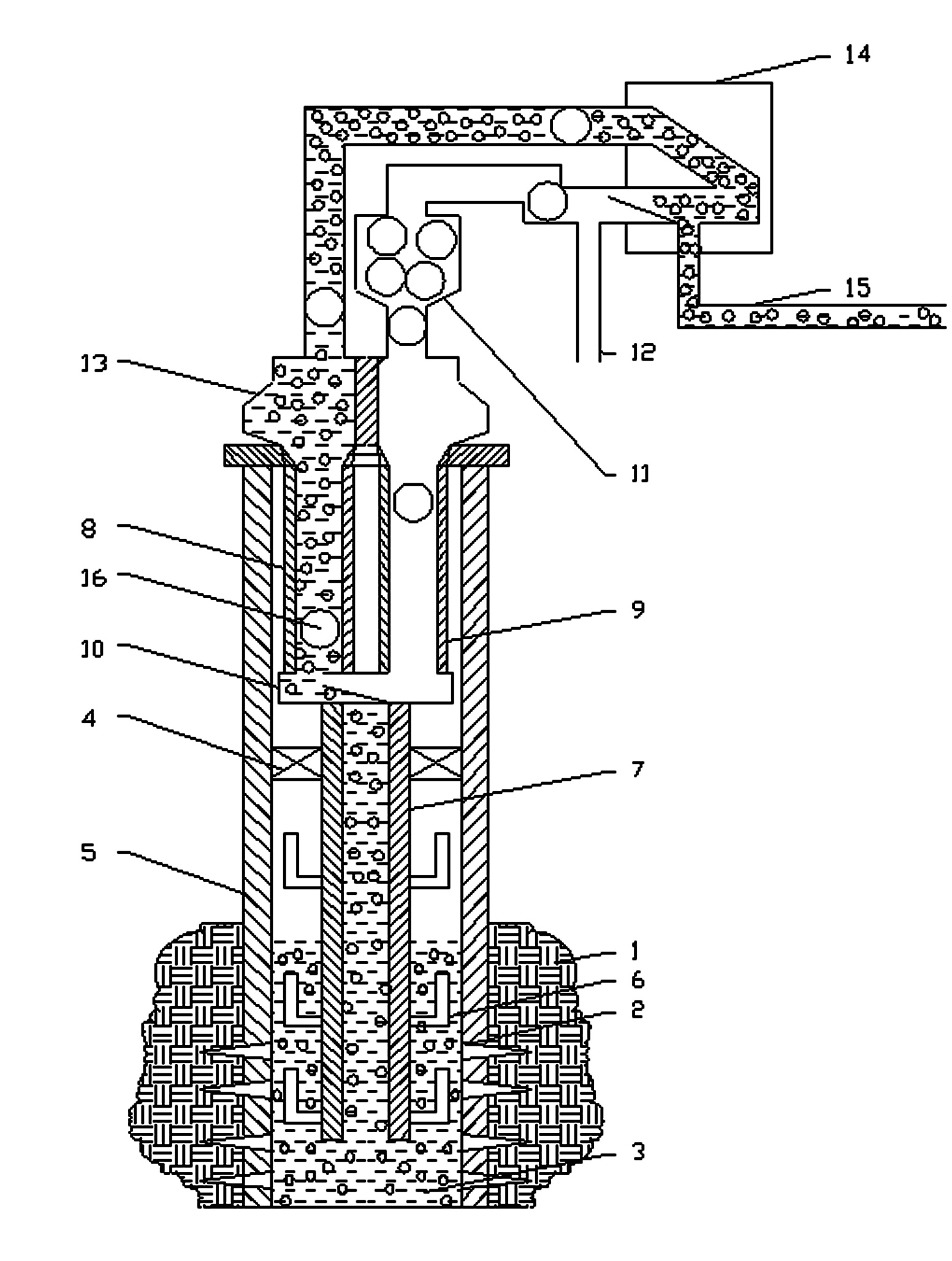
[0017] After applying the combined ball plug gas lift method, an independent chamber is formed between the bottom gas lift valve and the packer. As the gas pressure in the chamber increases, the gas lift valve is opened successively, and the gas enters the tubing, reducing the The density of the mixed liquid. Suppose the density of the liquid after mixing is 650kg / m 3 , keeping other parameters un...

example 2

[0021] Bottomhole fluid accumulation occurs at the bottom of the gas well. Assuming that the main components of the liquid are water and oil, the density of the liquid is 800kg / m 3 , the acceleration due to gravity is 10m 2 / s, the energy consumed by the damping force accounts for 20% of the output power, and the dynamic liquid level of the effusion is 3000m, which requires the ball plug gas lift to be lowered at least at a depth of 3500m. For conventional ball plug gas lift, it is necessary to start the system The required pressure is at least:

[0022] P n1 = ρgh / η =800×10×3500 / 0.8=35(Mpa)

[0023] After applying the combined ball plug gas lift method, the gas enters the oil pipe through the gas lift valve to reduce the density of the mixed liquid, assuming that the density of the mixed liquid is 650kg / m 3 . The plunge depth of the ball plug air lift is required to be at least 3500m. For the combined ball plug air lift, the pressure required to start the sys...


PUM

PropertyMeasurementUnit
Densityaaaaaaaaaa
Densityaaaaaaaaaa

Abstract

The invention provides a gas lift method of a combined ball plug for drainage and gas production of an oil and gas well, characterized in that: fluid in a stratum flows in a well bottom (3) through a perforation evelet (2), air in a packer (4), the well bottom and a production drivepipe (5) forms a high pressure, when the pressure reaches some limit, the high pressure gas can enter a bottom oil pipeline (7) through a bottom gas lift valve device (6), the high pressure gas and the fluid in the bottom oil pipeline (7) mix and lift to a bulb stopper lifting oil pipeline (8), gas lift balls (16) are supercharged by a gas injection pipeline (12), and enter a gas injection and gas lift ball falling oil pipeline (9) through a bat device (11) and enter the bulb stopper lifting oil pipeline (8) through a gas liquid mixer (10), the gas lift balls and the fluid flow a well opening oil extraction tree (13) and to a ball collector (14), the gas lift balls (16) flow to the ball collector (14) and are separated to the bat device (11), the fluid flows along with an output pipeline (15), small balls (16) are continuously thrown in the bat device (11), and the whole process goes round and round. The gas lift method of the combined ball plug has simple structure and high reliability and is suitable for most drainage and gas production wells. The gas lift valve is mounted at the bottom to use stratum energy adequately so that the lifting efficiency is higher and the production effect is good.

Description

technical field [0001] The invention relates to a liquid drainage and gas recovery method for oil and gas wells, in particular to a combined ball plug gas lift method. Background technique [0002] Gas reservoirs with edge and bottom water and condensate gas reservoirs are very common at home and abroad. During the production process, with the increase of recovery, the invasion, formation and output of edge and bottom water and condensate oil are often accompanied. Condensed water, condensed oil, and intruded formation water are very harmful to the exploitation of natural gas. As the formation energy gradually decreases, part of the liquid cannot be carried to the wellhead, and a large amount of liquid accumulates at the bottom of the well, forming fluid accumulation in the gas well. After bottomhole fluid accumulation, it will increase the back pressure on the production layer, reduce the production pressure difference and reduce the production capacity of the gas well. A...

Claims


Application Information

Patent Timeline
IPC IPC(8): E21B43/00
Inventor 顾岱鸿栾国华何顺利申颍浩谢全焦春燕
Owner CHINA UNIV OF PETROLEUM (BEIJING)
Why Eureka
Try Eureka