Combined LED lamp cup

A LED lamp cup and combined technology, which is applied to the damage prevention measures of lighting devices, lighting devices, cooling/heating devices of lighting devices, etc., can solve the problems of scratching and scalding human hands, improve the heat dissipation effect and reduce the quantity , The effect of increasing the flow rate

Inactive Publication Date: 2011-04-27
ZHEJIANG SHENGHUI LIGHTING
View PDF7 Cites 69 Cited by
  • Summary
  • Abstract
  • Description
  • Claims
  • Application Information

AI Technical Summary

Problems solved by technology

[0002] The structure of ordinary LED lights is as follows: figure 1 As shown, it includes a rubber base 21, in which an LED drive power supply 22 is accommodated, and a heat dissipation lamp cup 23 is arranged on the outer surface of the rubber base 21, and a plurality of heat dissipation fins 24 are longitudinally provided on the outer surface

Method used


Image

  • Combined LED lamp cup
  • Combined LED lamp cup
  • Combined LED lamp cup

Examples


Embodiment 1

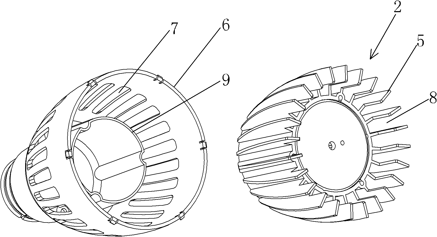
[0038] Embodiment 1: A combined LED lamp cup, such as figure 2 As shown, the heat dissipation device 2 is included, and a cavity is arranged inside the heat dissipation device 2, and a plurality of longitudinally arranged heat dissipation fins 5 are uniformly distributed on the outer surface of the heat dissipation device 2, and between any two adjacent heat dissipation fins 5 A heat dissipation channel 8 is formed, the lower end of the heat dissipation channel 8 is an air inlet, and a plastic shell 6 is provided on the outer cover of the heat dissipation device 2. The size and shape of the plastic shell 6 are just matched with the heat dissipation device 2, and can be just wrapped on the outside of the heat dissipation device 2; A plurality of heat dissipation holes 7 corresponding to the heat dissipation channels 8 are provided on the plastic housing 6 , and the number of the heat dissipation holes 7 is the same as the number of the heat dissipation channels 8 .

[0039] Th...

Embodiment 2

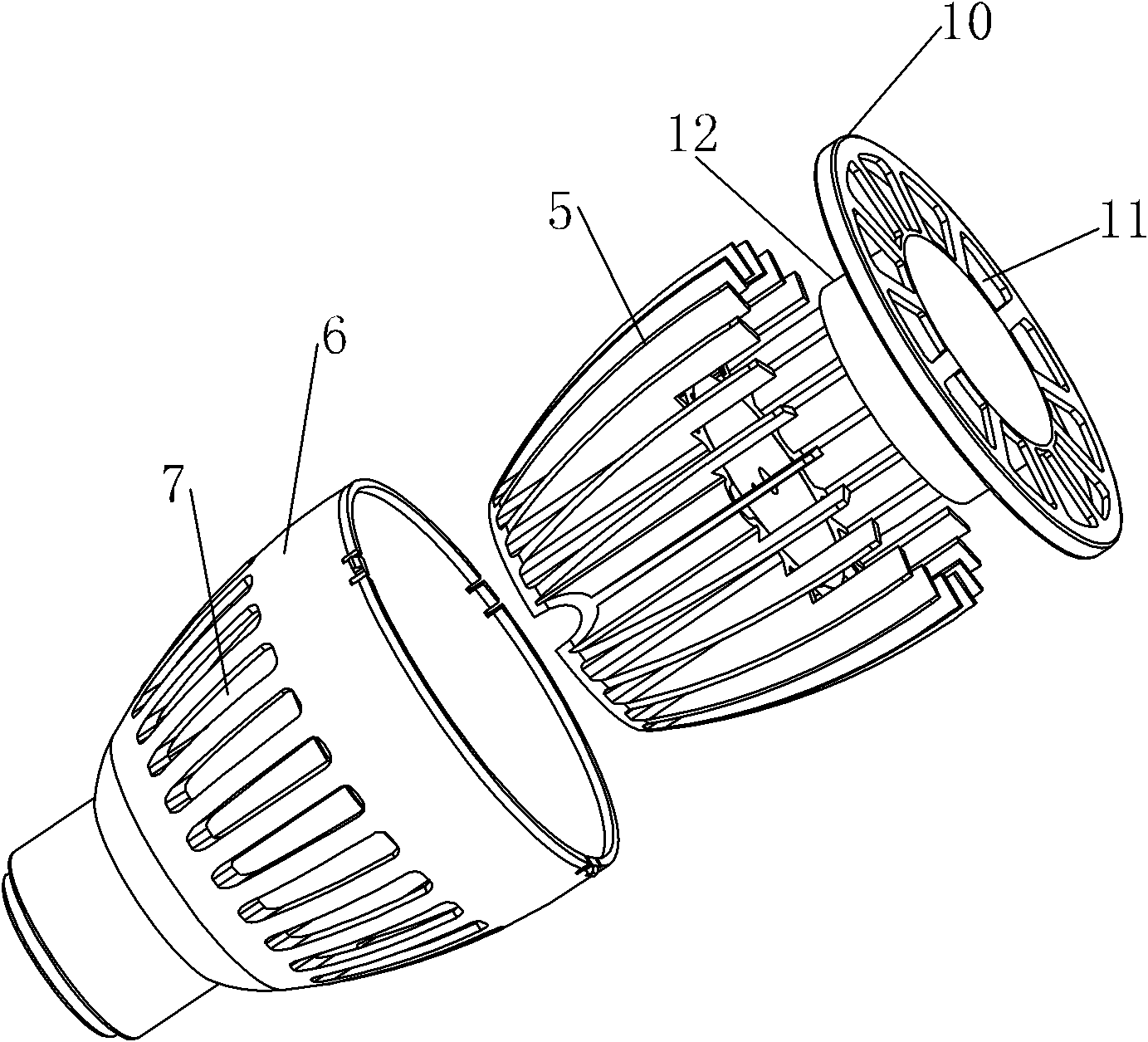
[0052] Embodiment 2: The difference between this embodiment and Embodiment 1 is that, as Figure 5 , Figure 6 As shown, the heat dissipation holes 7 are triangular in shape and arranged longitudinally. The width of the heat dissipation holes 7 gradually increases from bottom to top, and the number of heat dissipation holes 7 is the same as the number of heat dissipation channels 8 . The length of the cooling hole 7 is 15 mm, and the maximum width is 2.5 mm.

Embodiment 3

[0053] Embodiment 3: The difference between this embodiment and Embodiment 1 is that, as Figure 7 , Figure 8 As shown, the heat dissipation holes 7 are arc-shaped.


PUM

PropertyMeasurementUnit
Lengthaaaaaaaaaa
Widthaaaaaaaaaa
Thicknessaaaaaaaaaa

Abstract

The invention discloses a combined LED lamp cup, which comprises a radiating component. A cavity is formed inside the radiating component; a plurality of longitudinally arranged radiating fins are uniformly distributed on the outer surface of the radiating component; a plastic shell is sleeved outside the radiating component; and a plurality of radiating holes are formed on the plastic shell. Due to the arrangement of the plastic shell outside the radiating component, a user is effectively prevented from being scratched by edges of the radiating fins, and the user is prevented from being scalded by the surfaces of the radiating fins when a lamp works; moreover, a plurality of air ducts are formed through the radiating holes to force air to enter the radiating channel upwards from the lower end of the lamp cup and flow out of the radiating holes. Therefore, high-efficiency convection heat dissipation is formed, and compared with that of the conventional natural convection heat dissipation mode of exposing the lamp cup, the radiating effect is improved.

Description

technical field [0001] The invention relates to a lamp cup for an LED lamp, in particular to a combined LED lamp cup. Background technique [0002] The structure of ordinary LED lights is as follows: figure 1 As shown, it includes a rubber base 21, in which an LED drive power supply 22 is accommodated, and a heat dissipation lamp cup 23 is arranged on the outer surface of the rubber base 21, and a plurality of heat dissipation fins 24 are longitudinally provided on the outer surface of the heat dissipation lamp cup to dissipate heat. The front end of the lamp cup 23 is provided with a heat conducting plate 25, and a PCB circuit board 26 and a lens 27 are fixed with an LED light source. Processed, the heat dissipation fins 24 outside the heat dissipation lamp cup 23 have the hidden danger of scratching and scalding people's hands. Contents of the invention [0003] The present invention aims at the technical problems existing in the above-mentioned prior art, and provides...

Claims


Application Information

Patent Timeline
IPC IPC(8): F21S2/00F21V15/02F21V17/12F21V29/00F21Y101/02F21V29/77F21V29/83
Inventor 陈方沈晖梁玉栋
Owner ZHEJIANG SHENGHUI LIGHTING
Why Eureka
Try Eureka