
Starting and operating protection system of solar cavity type heat absorber

A protection system and heat absorber technology, applied in lighting and heating equipment, steam boiler components, steam boiler accessories, etc., can solve the problems of superheater burning, water shortage, easily damaged boiling tubes, etc., to speed up the start-up speed , to ensure safety and save the effect of startup time

Inactive Publication Date: 2011-04-27
XI AN JIAOTONG UNIV
View PDF5 Cites 9 Cited by
  • Summary
  • Abstract
  • Description
  • Claims
  • Application Information

AI Technical Summary

Problems solved by technology

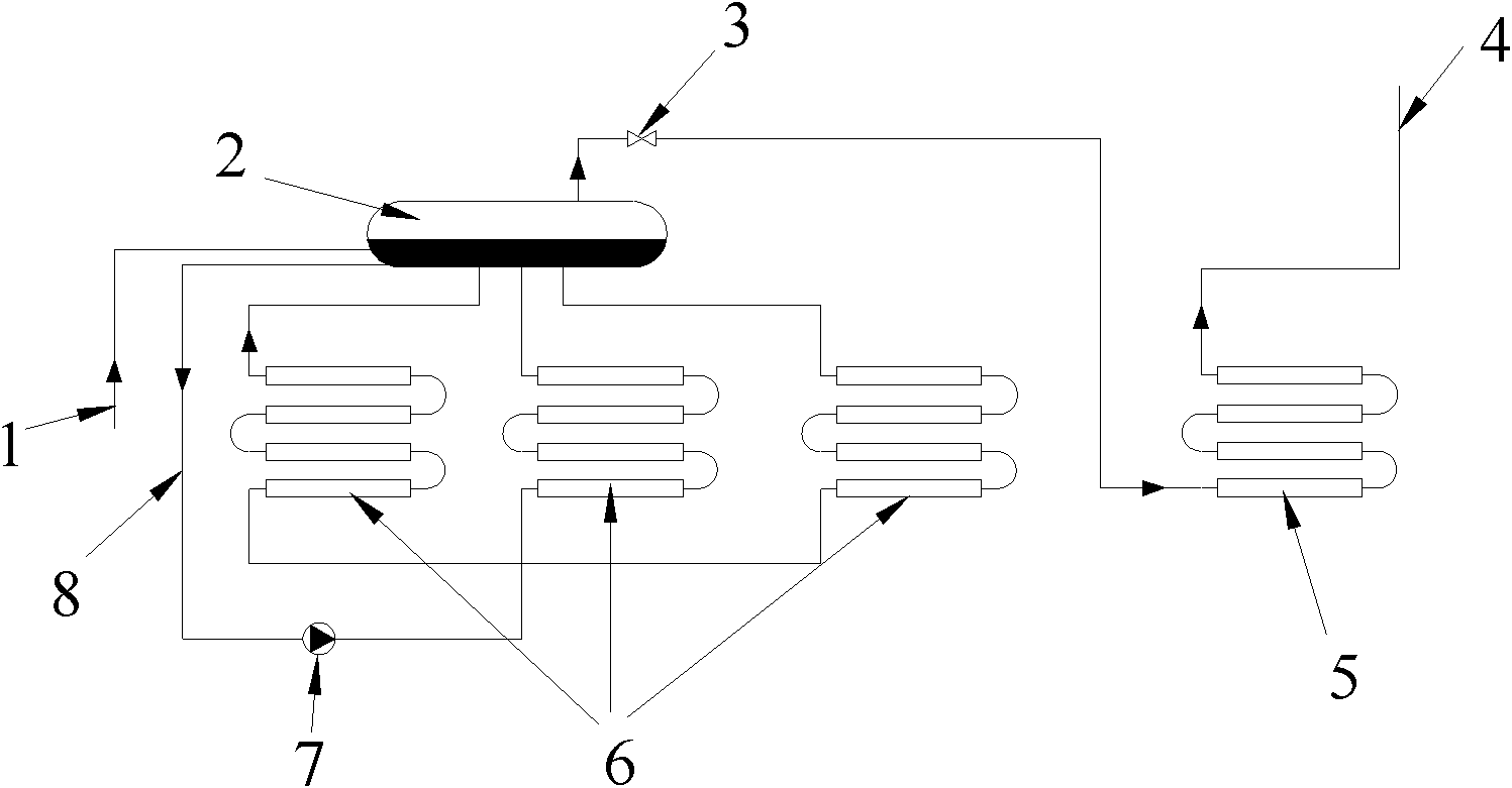
[0005] figure 1 There are two problems caused by the connection structure of the heat absorber: ① Due to the relatively high heat flux density inside the heat absorber, the steam-water circulation in the heat absorber generally adopts forced circulation to make the circulation in the pot have a higher cycle rate and ensure the safety of the boiling tube. However, a high-temperature circulation pump is needed to realize forced circulation, and the high-temperature circulation pump still has many technical problems at present, and it may be shut down due to serious failure. In the dry burning state, it is easy to damage the boiling tube; ②In the initial stage of the start-up of the heat absorber, the water in the heat absorber system is in a supercooled state, and no steam is generated, so that no gas enters the superheater, and the superheater is in a dry state at the beginning of start-up. Burning state, it is easy to burn the superheater

Method used


Image

  • Starting and operating protection system of solar cavity type heat absorber
  • Starting and operating protection system of solar cavity type heat absorber
  • Starting and operating protection system of solar cavity type heat absorber

Examples


Embodiment Construction

[0018] The present invention is described in further detail below in conjunction with accompanying drawing:

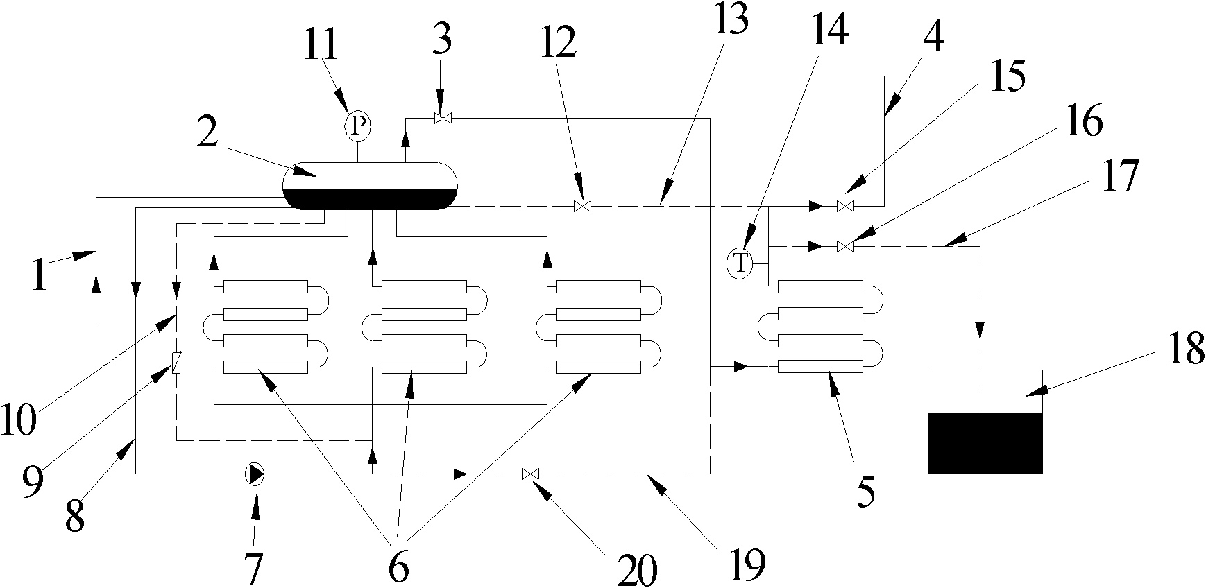
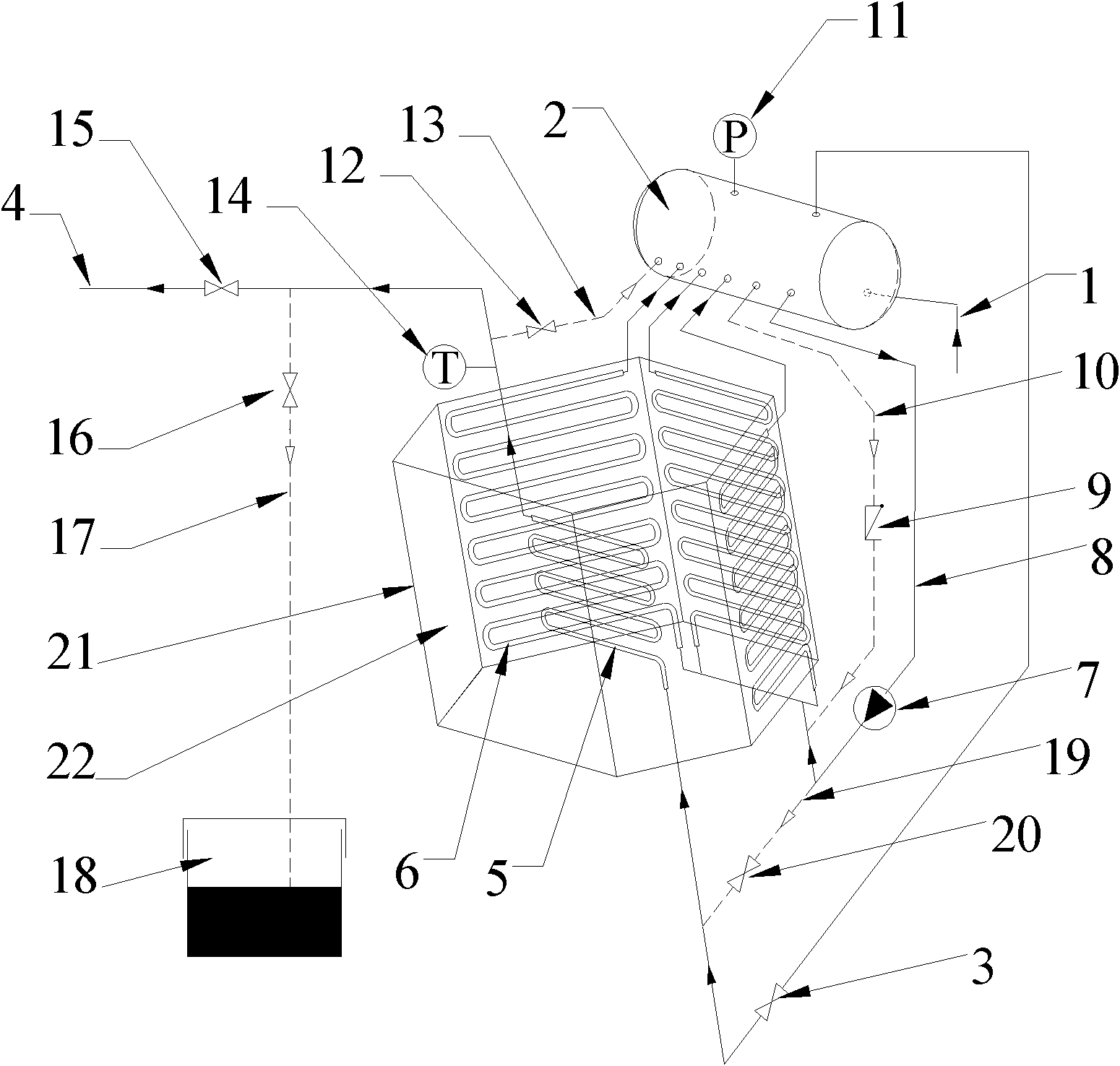
[0019] refer to figure 2 and image 3 , the protection system for the startup and operation of the solar cavity heat absorber of the present invention has two protection structures-the protection structure of the steam-water circulation in the pot of the cavity heat absorber and the protection structure of the superheater of the cavity heat absorber. figure 2 Shown in dotted line.

[0020] Wherein the first protection structure is the protection structure of the vapor-water circulation in the cavity heat absorber pot, which is combined by the downcomer 10 and the check valve 9 . Its specific structure is: a pipeline is connected in parallel next to the high-temperature circulation pump 7 of the steam-water circulation system in the pot of the cavity heat absorber, and the pipeline is directly connected to the drum 2 and the boiling tube 6 of the steam-water circula...


PUM


Abstract

The invention discloses a starting and operating protection system of a solar cavity type heat absorber. The starting and operating protection system of the solar cavity type heat absorber comprises a protection structure of a vapor-water circulating system in a cavity type heat absorber pot and a protection structure of a cavity type heat absorber superheater; the protection structure of the vapor-water circulating system in the cavity type heat absorber pot is that: a pipeline is connected in parallel beside a high-temperature circulating pump of the vapor-water circulating system in the cavity type heat absorber pot; and the pipeline is directly connected with a boiler barrel and a boiling tube of the vapor-water circulating system in the cavity type heat absorber pot to form a naturalcirculation loop of the vapor-water circulating system. The protection structure of the cavity type heat absorber superheater is that: an inlet and an outlet of the cavity type heat absorber superheater are provided with a protection bypass receptively. The starting and operating protection system of the solar cavity type heat absorber can make the cavity type heat absorber start and operate safely with high heat flux density and ensures that the cavity type heat absorber operates normally and smoothly and that the performance data of the cavity type heat absorber is acquired.

Description

technical field [0001] The invention belongs to the technical field of tower-type solar thermal power generation, and particularly relates to a protection system for starting and running of a solar cavity heat absorber, which is suitable for safe start-up and operation of the heat absorber in a tower-type solar thermal power generation system. Background technique [0002] Tower-type solar thermal power generation uses a large number of directional mirrors (heliostats) to gather sunlight to a central heat exchanger (heat absorber) installed on the top of the tower. The heat absorber heats the working fluid into steam and drives Turbine to generate electricity. According to the structure of the heat absorber, it can be divided into planar heat absorber and cavity heat absorber. The planar heat absorber arranges the heat absorber tubes on the outer surface of the heat absorber, while the cavity heat absorber arranges the heat absorber tubes on the inner surface of the heat ab...

Claims


Application Information

Patent Timeline
Patent Type & Authority Applications(China)
IPC IPC(8): F22B37/42F22B37/44
Inventor 郭烈锦魏进家张西民王跃社方嘉宾
Owner XI AN JIAOTONG UNIV
Learn More