

Refrigeration circulating system and application thereof
A circulating system and condenser technology, which is applied in refrigerators, refrigeration and liquefaction, and irreversible cycle compressors, etc., can solve the problems that the minimum capacity of the compressor cannot be reduced, and the maximum capacity cannot be increased, and achieves a simple and reasonable structure. Low-cost, wide-ranging effects
- Summary
- Abstract
- Description
- Claims
- Application Information
AI Technical Summary
Problems solved by technology
Method used
Image

Examples
no. 1 example
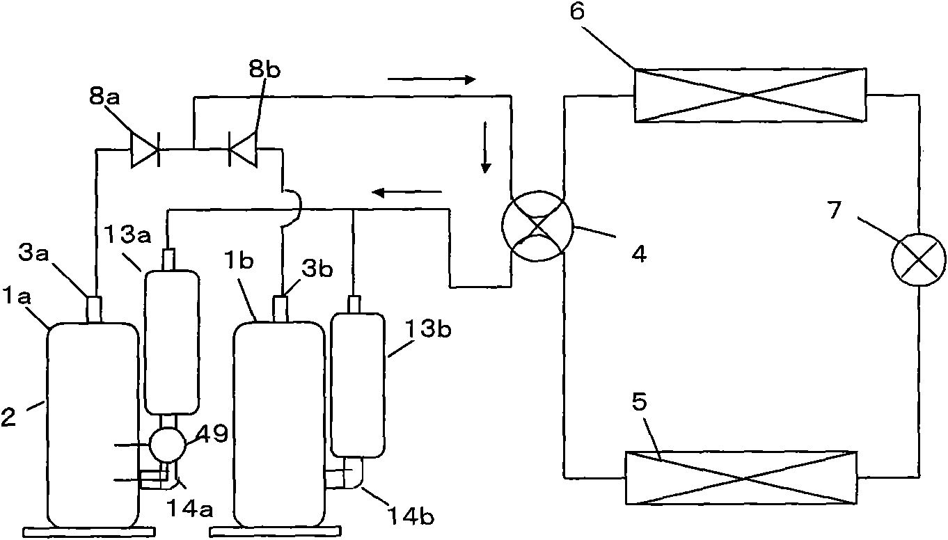
[0031] figure 1 A capacity-controlled single-cylinder type first rotary compressor 1a equipped with a variable cooling capacity through capacity control is shown, and a normal general fixed-capacity second rotary compressor that controls cooling capacity by continuation and stop of operation is shown. 1b refrigeration cycle.
[0032] In cooling mode, when both the first rotary compressor 1a and the second rotary compressor 1b are in operation, the refrigerant gas discharged from the first discharge pipe 3a and the second discharge pipe 3b of the two compressors passes through the The first check valve 8A and the second check valve 8b flow into the four-way switching valve 4, reach the outdoor heat exchanger 6, and become condensed refrigerant. Then, it passes through the expansion valve 7, evaporates in the indoor heat exchanger 5, and reaches the first liquid storage tank 13a and the second liquid storage tank 13b with respective compressors. Thereafter, the first suction p...
no. 2 example
[0059] In the second embodiment of the present invention, a capacity-controlled first rotary compressor and two fixed-capacity second and third rotary compressors without capacity control means are simultaneously mounted on an air conditioner or on the refrigeration system. results, such as Figure 7 As shown, compared with the first embodiment, the maximum value of the cooling capacity can be made larger. Moreover, like the first embodiment, the variable cooling capacity can be changed linearly and freely.
[0060] When the first rotary compressor, the second rotary compressor, and the third rotary compressor are simultaneously operated, this is called an A+B+C mode operation. As described above, by arbitrarily increasing the number of fixed-capacity rotary compressors, the number can be increased in a controllable manner while maintaining the cooling capacity variable means of the first embodiment.
[0061] Next, the gist of the invention will be described.
[0062] A si...
PUM
 Abstract
Description
Claims
Application Information