
Dynamic filter reactive power compensation device for fan converter cabinet

A technology of dynamic filtering and compensation device, applied in reactive power compensation, reactive power adjustment/elimination/compensation, harmonic reduction device, etc., to achieve the effect of good filtering effect, no transient impact, and simple use

Inactive Publication Date: 2011-04-27
JIAOZUO CITY TIANCHUANG ELECTRIC EQUIP
View PDF4 Cites 3 Cited by
  • Summary
  • Abstract
  • Description
  • Claims
  • Application Information

AI Technical Summary

Problems solved by technology

[0005] The technical problem to be solved by the present invention is the problem of high energy consumption of reactive power supplied from the generator set of the power supply system over a long distance

Method used


Image

  • Dynamic filter reactive power compensation device for fan converter cabinet
  • Dynamic filter reactive power compensation device for fan converter cabinet

Examples


Embodiment Construction

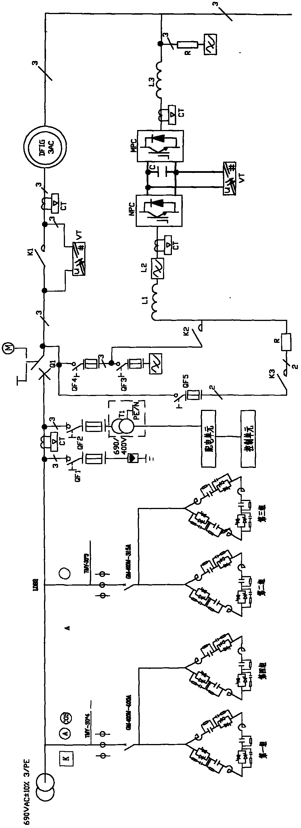
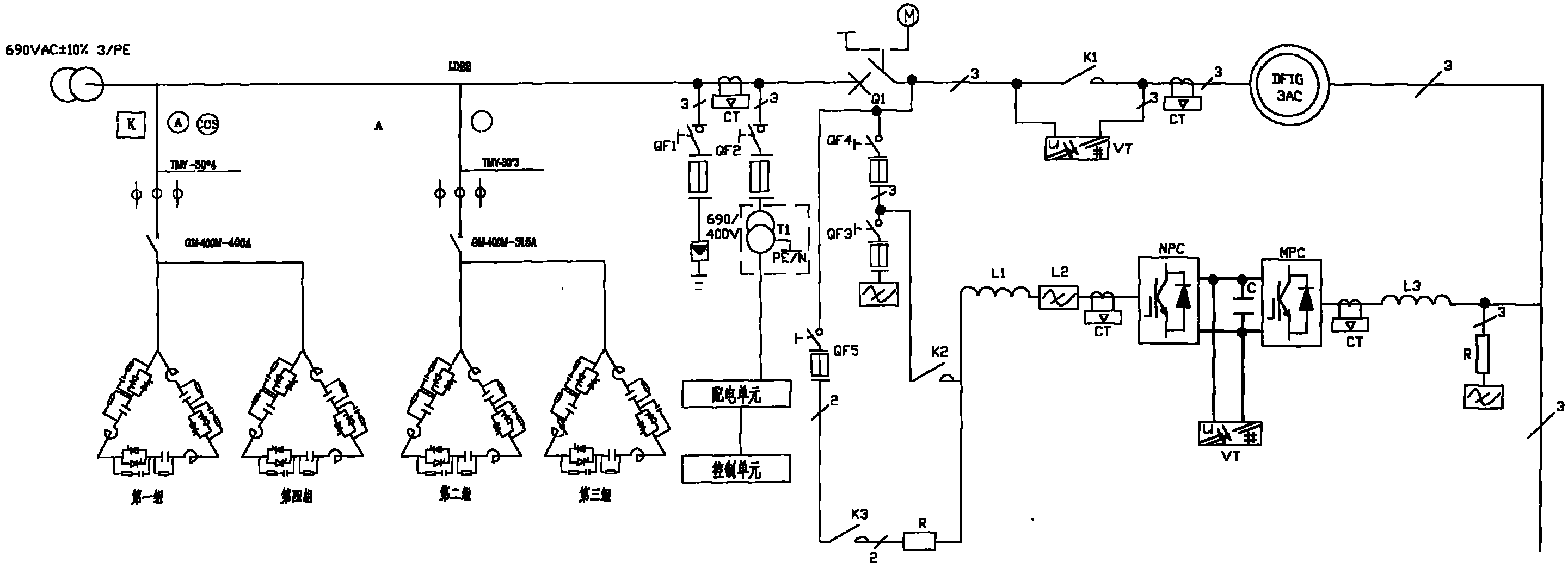
[0023] The dynamic filter reactive power compensation device of the fan converter cabinet of the present invention is composed of a control circuit and an LC filter circuit; the LC filter circuit is composed of three star-connected LC branches, and each LC branch is composed of a filter reactor, It is composed of filter capacitor, anti-parallel thyristor group and RC snubber circuit. The dynamic filter reactive power compensation device is connected to the output end of the converter cabinet and the power grid. The control circuit is composed of a power supply unit, a sensor signal processing unit, a trigger shutdown pulse signal unit, and a phase locker control unit; the power supply unit provides a stable power supply for the control circuit; the sensor signal processing unit detects the sensor in real time The received grid data is compared with the set parameters in the comparator, and then the control signal is sent to the trigger shutdown pulse signal unit after being pr...


PUM


Abstract

The invention discloses a dynamic filter reactive power compensation device for a fan converter cabinet. The dynamic filter reactive power compensation device is connected with the output end of the converter cabinet and an electric network. The dynamic filter reactive power compensation device consists of a control circuit and a liquid crystal (LC) filter circuit, wherein the LC filter circuit consists of three LC braches which adopt star connection; and each LC branch consists of a filter reactor, a filter capacitor, an anti-parallel thyristor group and a remote-control absorption circuit. The dynamic filter reactive power compensation device can effectively filter higher harmonics, so that waveform of the voltage and current of the electric network is returned to sine, the electrical environment is improved and purified, reactive power is provided for a system in real time, optimum reactive power compensation is realized, and the power factor of a user system is improved.

Description

technical field [0001] The invention relates to a dynamic filter free reactive power compensation device for a wind turbine converter cabinet. Background technique [0002] The development of power electronic technology, the wide application of power electronic equipment and the application of modern large-scale wind power generation equipment have brought profound changes to the development of electric power industry, manufacturing industry, transportation, information industry and other industries, and have become the national economic important part of the development. However, the accompanying harmonic pollution of the power grid and the consumption of inductive reactive power are also becoming more and more serious, which has reached the point where it must be treated and seriously resolved. [0003] The traditional control method is a capacitor switching contactor, which has a contactor composed of a power supply phase detection circuit, a charging circuit that can pr...

Claims


Application Information

Patent Timeline
Patent Type & Authority Applications(China)
IPC IPC(8): H02J3/01H02J3/18
CPCY02E40/30Y02E40/40
Inventor 李卫卫
Owner JIAOZUO CITY TIANCHUANG ELECTRIC EQUIP
Learn More