
Calculation Method of Reactive Power Compensation Capacitor Capacity in Distribution Network Containing Harmonics
A technology for compensating capacitors and calculation methods, which is applied in reactive power compensation, reactive power adjustment/elimination/compensation, calculation and other directions to achieve the effects of improving power quality, improving system reactive power, and improving the current status of grid reactive power overcompensation
- Summary
- Abstract
- Description
- Claims
- Application Information
AI Technical Summary
Problems solved by technology
Method used
Image

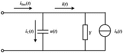
Examples
Embodiment 1
[0069] Select a 10kV line in a substation, the power supply voltage is distorted, and the load is a linear load; when the system is not compensated, the three-phase voltage distortion rate of the 10kV bus is 4.66%, and the current distortion rate is 1.08%. Taking phase A as an example, the measured The harmonic content value (phase voltage amplitude) is shown in Table 1.
[0070] Table 1 Bus voltage and current harmonic content values
[0071]
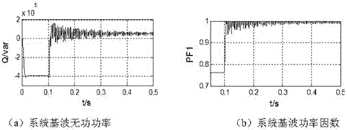
[0072] When compensating according to the traditional sinusoidal reactive power definition, the capacitor capacitance value C is calculated 传 =10.262μF; when compensated according to the proposed method, the calculated capacitor capacitance C opt =10.262μF; input two sets of capacitor banks calculated by the compensation algorithm (the reactance rate is 5%), and the simulation diagram of the system’s fundamental reactive power and fundamental power factor can be obtained respectively, as shown in the attached image 3 shown.
[0...
Embodiment 2
[0075] Select a 10kV line in a substation, ignore the harmonics of the supply voltage, and the load is a nonlinear load; when the system is not compensated, the three-phase voltage distortion rate of the 10kV bus is 1.57%, and the current distortion rate is 35.03%. Taking the A phase as an example, The measured harmonic content values (phase voltage amplitude) are shown in Table 2.
[0076] Table 2 Bus Voltage and Current Harmonic Content Values
[0077]
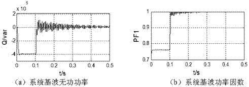
[0078] When compensating according to the traditional sinusoidal reactive power definition, the capacitor capacitance value C is calculated 传 =12.954μF; when compensated according to the proposed method, the calculated capacitor capacitance value C opt =10.806μF; put into two sets of capacitor banks calculated by the compensation algorithm (the reactance rate is 5%), and the simulation diagram of the change of the fundamental reactive power and fundamental power factor of the system can be obtained respectively, as sho...
Embodiment 3
[0081] A 10kV line in a substation is selected, the power supply voltage is distorted, and the load is a nonlinear load; when the system is not compensated, the three-phase voltage distortion rate of the 10kV bus is 3.71%, and the current distortion rate is 50.89%. Taking Phase A as an example, the measured harmonic content values (phase voltage amplitude) are shown in Table 3.
[0082] Table 3 Bus voltage and current harmonic content values
[0083]
[0084] When compensating according to the traditional sinusoidal reactive power definition, the capacitor capacitance value C is calculated 传 =14.497μF; when compensated according to the proposed method, the capacitor capacitance value C is calculated opt = 11.021μF; input two sets of capacitor banks calculated by the compensation algorithm (the reactance rate is 5%), and the simulation diagram of the change of the fundamental reactive power and fundamental power factor of the system can be obtained respectively.
[0085]...
PUM
 Abstract
Description
Claims
Application Information