

Capacity calculating method for power distribution network reactive compensation capacitor containing harmonic waves
A compensation capacitor and calculation method technology, applied in reactive power compensation, reactive power adjustment/elimination/compensation, calculation, etc., can solve problems such as overcompensation
- Summary
- Abstract
- Description
- Claims
- Application Information
AI Technical Summary
Problems solved by technology
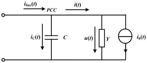
Method used
Image

Examples
Embodiment 1
[0061] Select a 10kV line in a substation, its power supply voltage is distorted, and the load is a linear load; when the system is not compensated, the three-phase voltage distortion rate of the 10kV bus is 4.66%, and the current distortion rate is 1.08%. Taking phase A as an example, the measured The harmonic content value (phase voltage amplitude) is shown in Table 1.
[0062] Table 1 Bus voltage and current harmonic content values
[0063]
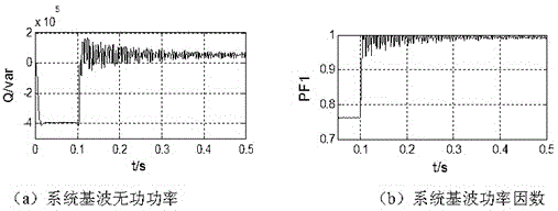
[0064] When the compensation is defined by the traditional sinusoidal reactive power, the calculated capacitance value of the capacitor C 传 =10.262 μF ; When compensated according to the proposed method, the capacitance value of the capacitor is calculated C opt =10.262 μF ; Putting two sets of capacitor banks (with a reactance rate of 5%) calculated by the compensation algorithm, the simulation diagrams of the system’s fundamental reactive power and fundamental power factor changes can be obtained, as shown in the attached ...
Embodiment 2
[0067] Select a 10kV line in a substation, ignore the harmonics of the supply voltage, and the load is a non-linear load; when the system is not compensated, the three-phase voltage distortion rate of the 10kV bus is 1.57%, and the current distortion rate is 35.03%. Taking phase A as an example, The measured harmonic content values (phase voltage amplitude) are shown in Table 2.
[0068] Table 2 Bus Voltage and Current Harmonic Content Values
[0069]
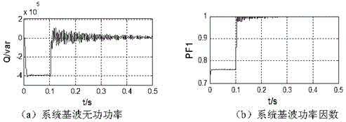
[0070] When the compensation is defined by the traditional sinusoidal reactive power, the calculated capacitance value of the capacitor C 传 =12.954 μF ; When compensated according to the proposed method, the capacitance value of the capacitor is calculated C opt =10.806 μF ; Putting two sets of capacitor banks (with a reactance rate of 5%) calculated by the compensation algorithm, the simulation diagrams of the system’s fundamental reactive power and fundamental power factor changes can be obtained, as shown in the ...
Embodiment 3
[0073] The 10kV line of a substation is selected, the power supply voltage is distorted, and the load is a nonlinear load; when the system is not compensated, the three-phase voltage distortion rate of the 10kV bus is 3.71%, and the current distortion rate is 50.89%. Taking phase A as an example, the measured harmonic content values (phase voltage amplitude) are shown in Table 3.
[0074] Table 3 Bus voltage and current harmonic content values
[0075]
[0076] When the compensation is defined by the traditional sinusoidal reactive power, the calculated capacitance value of the capacitor C 传 =14.497 μF ; When compensated according to the proposed method, the capacitance value of the capacitor is calculated C opt =11.021 μF ; put into the two sets of capacitor banks calculated by the compensation algorithm (the reactance rate is 5%), and the simulation diagram of the change of the fundamental reactive power and fundamental power factor of the system can be obtained ...
PUM
 Abstract
Description
Claims
Application Information