Dust dumping structure for dust-collecting bucket

A technology of dust collection bucket and bucket body, which is applied in the direction of suction filter, etc., which can solve the problems affecting customer satisfaction, inconvenient operation, and rising dust, and achieve the effect of preventing dust splashing, improving satisfaction, and simple locking

Inactive Publication Date: 2011-05-04
LG ELECTRONICS (TIANJIN) APPLIANCES CO LTD
View PDF0 Cites 3 Cited by
  • Summary
  • Abstract
  • Description
  • Claims
  • Application Information

AI Technical Summary

Problems solved by technology

The existing bottom opening dumping separator requires one hand to hold the handle of the dust bucket and the other hand to press the button when the customer dumps the dust, which is inconvenient to operate; in addition, when the button is pressed, the bottom cover is Rapidly falling, causing dust to rise instantaneously, causing hygiene problems and affecting customer satisfaction

Method used


Image

  • Dust dumping structure for dust-collecting bucket
  • Dust dumping structure for dust-collecting bucket
  • Dust dumping structure for dust-collecting bucket

Examples


Embodiment Construction

[0029] Below in conjunction with accompanying drawing and specific embodiment the present invention is described in further detail:

[0030] The working principle of the vacuum cleaner of the present invention is the same as that of the prior art, and the prior art can be referred to, so it will not be described again, and the same symbols as those of the prior art will be used. The differences between the present invention and the prior art will be described below Detailed explanation:

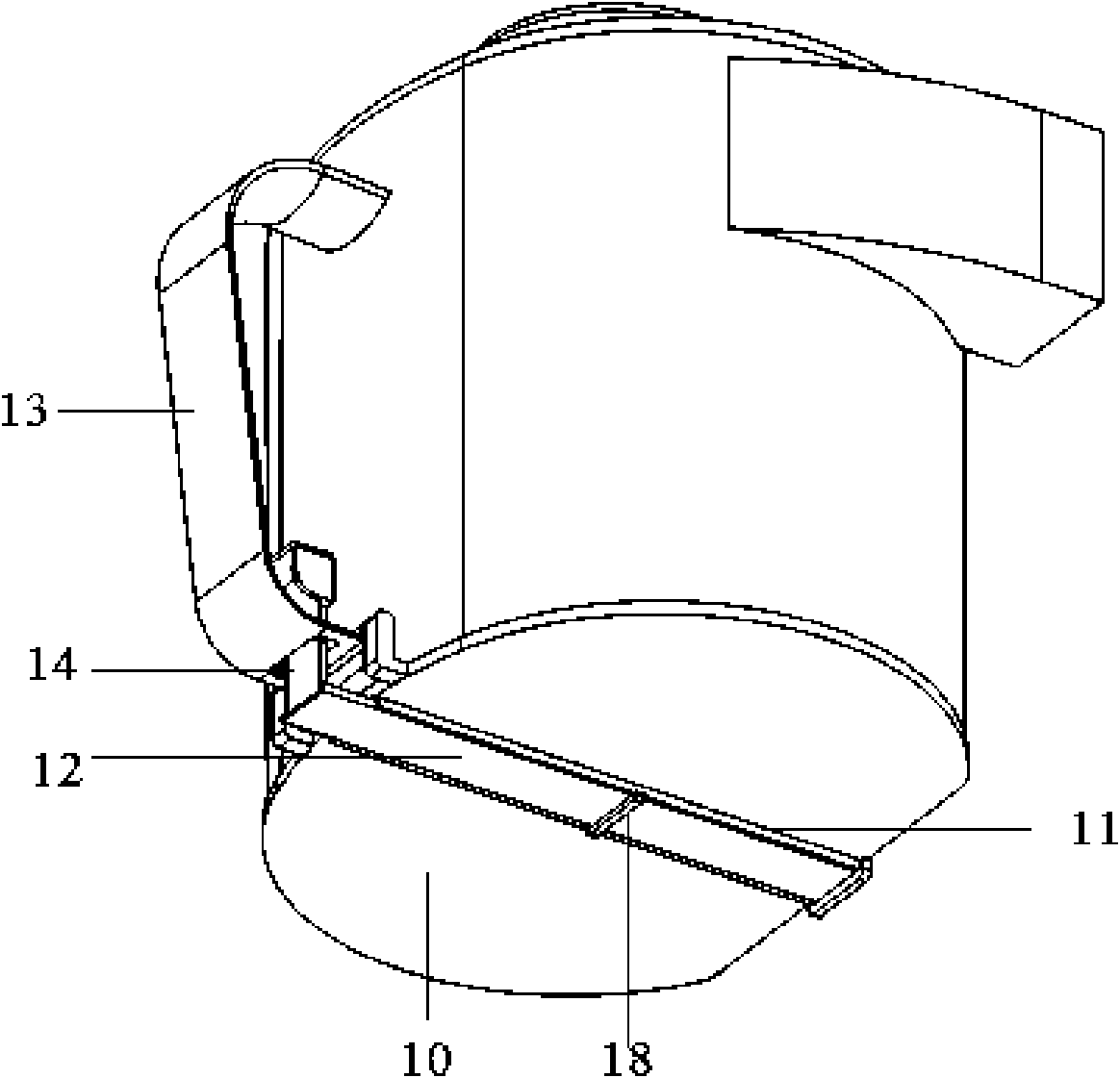
[0031] First, the first embodiment of the present invention will be described in conjunction with FIG. 25. A rectangular through hole is formed through the lower part of the handle 13, and groove slides 15 are formed on the inner side walls of the through hole, through which the brake arm 14 of the button 19 passes. The tongue 16 correspondingly formed on both sides of the brake arm 14 is slidably fixed in the groove slideway 15, and the groove slides to cooperate with the tongue so that the ...


PUM


Abstract

The invention discloses a dust dumping structure for a dust-collecting bucket. The dust-collecting bucket comprises a dust-collecting bucket body in which a dust separating and storing assembly is arranged, and a handle formed on the upper part of the bucket body; the dust-collecting bucket also comprises a bottom cover capable of sealing the dust-collecting bucket in an opening / closing mode, and a pull piece slidably fixed on the lower surface of the bottom cover; one end of the pull piece is hinged with a brake arm of a button; a free end of the pull piece is separately inserted into a locking hole; and the button is slidably fixed on the handle. The invention has simple locking function and can control the opening speed of the bottom cover so as to effectively prevent dust from flying; it is clean and sanitary to dump the dust in the dust-collecting bucket, hands of a customer are prevented from contacting the polluted lower cover, the degree of satisfaction of the customer is improved; and the invention has a simple operating mechanism and high productivity.

Description

technical field [0001] The invention relates to a vacuum cleaner, in particular to a novel dust collecting bucket. Background technique [0002] Generally, a vacuum cleaner is a device that uses a motor to generate suction to inhale air, make the air flow through various filters, filter foreign objects in the air, and clean the room. [0003] Generally speaking, a vacuum cleaner mainly includes a suction device and a suction pipeline. The suction device mainly formed by a motor and a fan is arranged in the body. The suction pipeline includes a suction head and a suction pipe. The suction head has a downward opening. The suction port communicates with the air inlet of the fan inside the body through the telescopic pipe and the flexible pipe of the suction pipe. When the vacuum cleaner is running, the motor drives the impeller of the fan to rotate at a high speed, exhausting the air in the vacuum cleaner, forming an instantaneous vacuum in the vacuum cleaner, and forming a re...

Claims


Application Information

Patent Timeline
Patent Type & Authority Applications(China)
IPC IPC(8): A47L9/10
Inventor 刘明明肖宗亮
Owner LG ELECTRONICS (TIANJIN) APPLIANCES CO LTD
Why Eureka
Try Eureka