

Storage clamp at automobile
A technology for storage and automobiles, which is applied in the field of storage clips and storage clips on automobiles. It can solve the problems that elastic clips cannot be used as car storage clips, cannot hold mineral water bottles, and the clamping force of elastic clips is small. Effects of improving aesthetics, reducing thickness, and preventing abnormal noise
- Summary
- Abstract
- Description
- Claims
- Application Information
AI Technical Summary
Problems solved by technology
Method used
Image

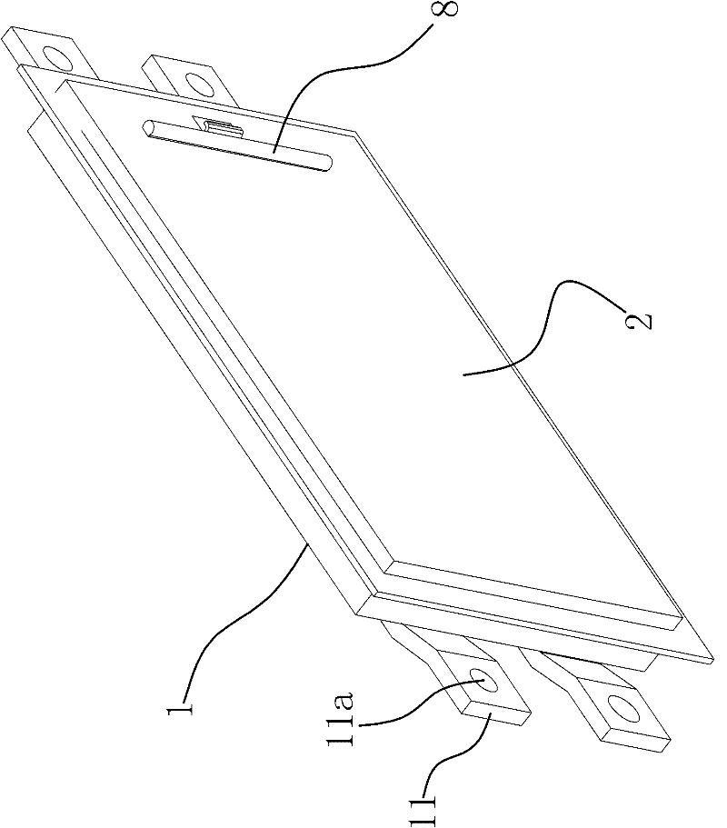
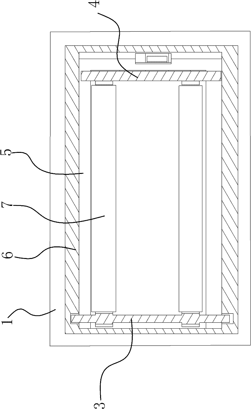
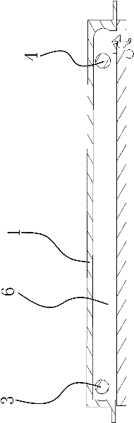
Examples
Embodiment 1
[0023] Such as figure 1 , figure 2 and image 3 As shown: the storage clip on the car includes a fixed plate 1, on which an elastic splint 2 is arranged. Specifically, the splint 2 is made of polyamide 66 material. Two fixed shafts 3 and moving shafts 4 parallel to each other are fixed on the two edges of the splint 2. Specifically, the fixed shaft 3 and the splint 2 are in an integrated structure, and the moving shaft 4 and the splint 2 are in an integrated structure. The splint 2 is hinged on the fixed plate 1 through the fixed shaft 3, and a guide structure is provided between the fixed plate 1 and the splint 2 to make the moving shaft 4 slide to the fixed shaft 3.
[0024] Specifically, the guide structure is a groove 5 provided on the fixed plate 1, and guide grooves 6 are respectively opened on the opposite side walls of the groove 5, and the two ends of the above-mentioned moving shaft 4 are respectively arranged in the two guide grooves. within 6. The moving shaft...
Embodiment 2
[0029] The content in the second embodiment is roughly the same as that in the first embodiment, the difference is that the guide structure in the first embodiment is a groove 5 provided on the fixed plate 1, on the opposite side walls of the groove 5 Guide grooves 6 are provided respectively, and the two ends of the above-mentioned moving shaft 4 are respectively arranged in the two guide grooves 6; while the guide structure in the second embodiment is two ring-shaped guide rails fixed on the fixed plate 1, the above-mentioned Both ends of the moving shaft 4 are respectively arranged in two annular guide rails. The moving shaft 4 is arranged in the ring guide rail, so that the moving shaft 4 can only slide in the ring guide rail without breaking away from the ring guide rail.
PUM
 Abstract
Description
Claims
Application Information