Horizontal U-shaped fin tube heat exchanger of air source heat pump and fixing mode thereof

A technology of finned tube heat exchangers and air source heat pumps, applied in heating methods, space heating and ventilation details, household heating, etc., can solve problems such as high pressure in high-voltage operation of the system, tripping protection, and clean flow. Achieve the effects of reducing height space, uniform thermal power, and controlling uniformity

Inactive Publication Date: 2011-05-04
劳特斯空调(江苏)有限公司
View PDF0 Cites 7 Cited by
  • Summary
  • Abstract
  • Description
  • Claims
  • Application Information

AI Technical Summary

Problems solved by technology

However, due to the installation and structural problems of the traditional finned heat exchanger, the melted water generated by the defrosting in the upper part of the heat exchanger flows to the lower part with the action of gravity, and the melted water will not flow clean after the defrosting cycle due to the defrosting cycle. Enter the next heating cycle
This phenomenon is especially obvious in the air source heat pump air conditioning system with the upper air outlet mode. The main reason is that there are differences in the wind speed of the upper, middle and lower parts of the heat exchanger, resulting in uneven heat transfer efficiency and fin heat transfer. The original frosting on the surface of the device is uneven
In this way, the frost on the lower part of the heat exchanger gradually deteriorates over and over again, which cannot effectively improve the heat exchange efficiency, and may even cause liquid return to the compressor due to poor heat exchange effect, resulting in liquid leakage from the compressor.
At the same time, during the defrosting process, some branch pipes (mainly concentrated in the lower part of the heat exchanger) cannot effectively defrost due to thermodynamic reasons during the operation of the refrigerant, while the defrosting of other branch pipes is completed, resulting in a relatively high operating pressure of the system at this time , a tripping protection phenomenon occurs

Method used


Image

  • Horizontal U-shaped fin tube heat exchanger of air source heat pump and fixing mode thereof
  • Horizontal U-shaped fin tube heat exchanger of air source heat pump and fixing mode thereof
  • Horizontal U-shaped fin tube heat exchanger of air source heat pump and fixing mode thereof

Examples


Embodiment Construction

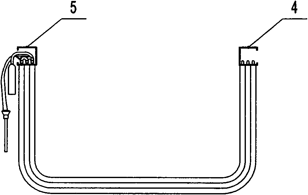
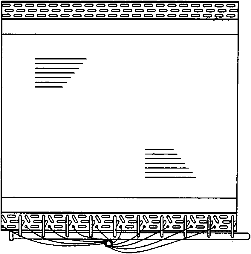
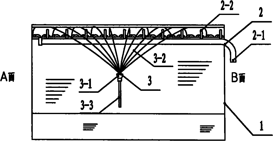
[0019] Such as figure 1 , figure 2 with image 3 As shown, the horizontal U-shaped finned tube heat exchanger includes a U-shaped finned tube heat exchanger 1, an air collecting tube assembly 2, a liquid distributor assembly 3, and an end installed at the upper end of the U-shaped finned tube heat exchanger. Plate I 4. End plate II5. The gas collecting pipe assembly 2 includes a gas collecting pipe 2-1 and a distribution pipe 2-2 welded to the gas collecting pipe; the liquid distributor assembly 3 includes a liquid distributor 3-1, a liquid distributor 3-2 and a liquid distributor connecting pipe 3 -3, where the distributor connecting pipe 3-3 is brazed and connected with the liquid inlet hole below the liquid distributor 3-1, and the liquid distributor pipe 3-2 is brazed and connected with the liquid hole above the liquid distributor 3-1; U-shape The opening of the fin tube heat exchanger 1 is upward, and the gas collector assembly 2 is placed horizontally. The gas collector ...


PUM


Abstract

The invention discloses a novel U-shaped fin tube heat exchanger and a fixing mode thereof. A common U-shaped fin tube heat exchanger is designed into a horizontal U-shaped heat exchanger with an upward opening, a gas collecting tube assembly is horizontally arranged, the gas collecting tube assembly and a dispenser assembly are respectively assembled outside one side of the fin tube heat exchanger, and an end plate I and an end plate II are respectively shaped into a U-shaped structure. The invention has the advantages of ensuring that pressure drops of refrigerants of all refrigerant loops are consistent and wind circulation of each refrigerating system is more uniform, effectively solving the problem of nonuniform defrosting of heat exchangers adopting other fixing modes, and reducing the height of the whole set because an outdoor condensing fan blade and a motor are installed in a space in the U-shaped fin tube heat exchanger.

Description

Technical field [0001] The invention belongs to the technical field of refrigeration and air conditioning. Specifically, it is an air source heat pump horizontal U-shaped finned tube heat exchanger and its fixing method. Background technique [0002] Air source heat pumps are widely promoted and applied in the air-conditioning industry mainly because of their excellent heat exchange performance and the randomness of the installation location. At present, the installation forms of outdoor fin heat exchangers have the following forms: [0003] 1. Vertical installation of U-shaped and L-shaped heat exchangers; [0004] 2. Vertical installation of straight heat exchanger; [0005] 3. V-type heat exchanger; [0006] 4. W-type heat exchanger; [0007] As for the large cooling capacity air-cooled heat pump unit, most of the top air outlet, the fan and the motor are arranged on the top plate of the unit. In this case, the above four heat exchanger installation forms have a height difference b...

Claims


Application Information

Patent Timeline
Patent Type & Authority Applications(China)
IPC IPC(8): F25B39/00F24F13/30
Inventor 唐钧庆成义陈昭晖陈振乾徐松
Owner 劳特斯空调(江苏)有限公司
Why Eureka
Try Eureka