
Antenna with grounded U-shaped high-impedance surface metal strips and wireless communication device

A high-impedance surface and metal strip technology, applied in the direction of antenna grounding devices, antennas, electrical short antennas, etc., can solve the problems of great influence, lower specific absorption rate, lack of versatility and universal practicability, etc., to reduce radiation , reduce the specific absorption rate, reduce the effect of radiation energy

Active Publication Date: 2011-05-04
成武县启源国有资产运营有限责任公司
View PDF4 Cites 5 Cited by
  • Summary
  • Abstract
  • Description
  • Claims
  • Application Information

AI Technical Summary

Problems solved by technology

[0003] At present, mobile terminals have been designed to be used within these extremely strict limits, so various devices and methods for reducing SAR are being developed; for example, attaching electromagnetic wave-absorbing materials to mobile terminals, or The layout of the optimized radio frequency induction current, and complex antenna design are used to reduce the specific absorption rate, etc. However, these design methods are often greatly affected by the type of mobile terminal, and are not universal and universally applicable
[0004] Therefore, the existing technology still needs to be improved and developed

Method used


Image

  • Antenna with grounded U-shaped high-impedance surface metal strips and wireless communication device
  • Antenna with grounded U-shaped high-impedance surface metal strips and wireless communication device
  • Antenna with grounded U-shaped high-impedance surface metal strips and wireless communication device

Examples


Embodiment Construction

[0024] The specific implementations and examples of the present invention will be described in detail below in conjunction with the accompanying drawings. The described specific examples are only used to explain the present invention, and are not intended to limit the specific implementations of the present invention.

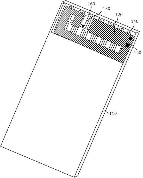
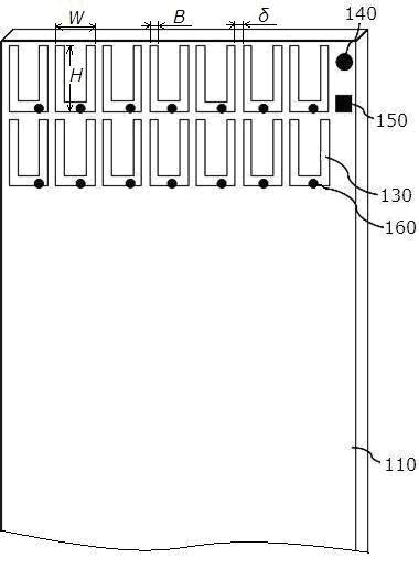
[0025] A grounded antenna with a U-shaped high-impedance surface metal strip of the present invention, one of its specific implementation methods, such as figure 1 As shown, it includes an antenna radiating unit 120 and its grounding plate 110; wherein, a plurality of high-impedance surface units are arranged at intervals on the grounding plate 110; each high-impedance surface unit is composed of three sections of high-impedance surface metal strips 130. font; the high-impedance surface metal strip 130 on the U-shaped bottom edge is provided with a high-impedance surface via hole 160; the high-impedance surface metal strip 130 between the high-impedance surface ...


PUM

PropertyMeasurementUnit
Line widthaaaaaaaaaa
Heightaaaaaaaaaa

Abstract

The invention discloses an antenna with grounded U-shaped high-impedance surface metal strips and a wireless communication device with the antenna. The antenna is arranged in a housing, and comprises an antenna radiation unit and a grounding plate thereof. A plurality of high-impedance surface units are arranged at intervals on the grounding plate, and each high-impedance surface unit consists ofthree sections of high-impedance surface metal strips which are connected to form a U shape. High-impedance surface through holes are formed on the bottom edges of the U shapes, and are used for connecting the high-impedance surface metal strips among the high-impedance surface units. Due to the adoption of the plurality of U-shaped high-impedance surface units, the antenna and the wireless communication device suppress or prevent surface waves from being propagated along the surface of the antenna on one hand, and perform same-phase reflection on plane waves incident vertically to the surface of the antenna on the other hand; the antenna and the wireless communication device reduce radiation on a head, reduce radiation energy absorbed by the head and reduce a specific absorption rate by utilizing the surface wave suppression characteristics of the high-impedance surface units arranged around the antenna; and simultaneously, the radiation performance of the antenna may not be reduced,the communication quality may not be influenced, and the antenna and the wireless communication device have universality and universal applicability.

Description

technical field [0001] The invention relates to the antenna field of wireless communication devices, and more specifically, the improvement relates to an antenna with a U-shaped high-impedance surface metal strip grounded and a wireless communication device thereof. Background technique [0002] The radio waves emitted by wireless communication devices during the communication process expose users to measurable radio frequency electromagnetic radiation; for example, when using a mobile terminal such as a mobile phone to make a call, the head is often placed in the electromagnetic radiation field emitted by the mobile phone ; For this reason, the governments of various countries, including China, have formulated comprehensive and safe guidelines and regulations to manage and restrict the exposure of radio frequency energy; among them, the specific absorption rate (SAR, Specific Absorption Rate) is a very important evaluation parameter , which means the electromagnetic wave ab...

Claims


Application Information

Patent Timeline
IPC IPC(8): H01Q1/48H04M1/02
CPCH01Q1/245H01Q15/006H01Q9/0421H01Q15/008H01Q17/008
Inventor 张莲
Owner 成武县启源国有资产运营有限责任公司
Learn More