Control system and method of illumination equipment

A lighting equipment and control system technology, applied in lighting equipment control system and its control field, can solve problems such as occasions where long-term lighting cannot be applied, the service life of lighting equipment can be reduced, and energy saving requirements cannot be achieved.

Inactive Publication Date: 2011-05-04
ZHONGSHAN XINGHAN TECH
View PDF4 Cites 4 Cited by
  • Summary
  • Abstract
  • Description
  • Claims
  • Application Information

AI Technical Summary

Problems solved by technology

[0002] For a long time, people have been exploring to make lighting equipment more intelligent, more convenient to use, and more energy-saving. However, most of the current lighting equipment still requires human control, and there are some lighting control systems such as: voice-activated, inductive, etc. , the limitations of its use are also very large, and it cannot be applied to occasions that require long-term lig

Method used


Image

  • Control system and method of illumination equipment
  • Control system and method of illumination equipment
  • Control system and method of illumination equipment

Examples


Embodiment Construction

[0042] Below in conjunction with accompanying drawing, the present invention is described in detail:

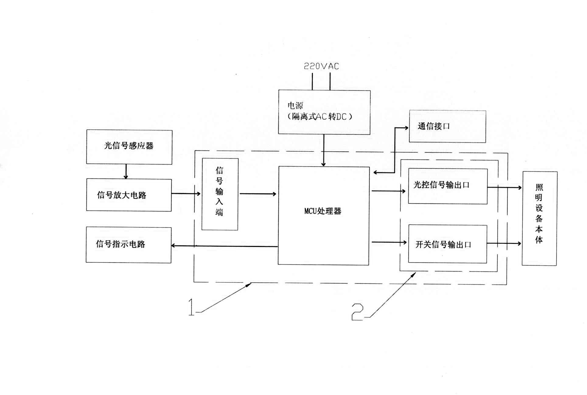
[0043] figure 1 It is a system composition diagram of the present embodiment, as can be seen from the figure:

[0044] This embodiment consists of a lighting device body, a central processing unit 1, an induction unit and a power supply. The induction unit in this embodiment is an optical signal sensor, and the power supply is an isolated AC-to-DC power supply with an input voltage of 220V. The central The processing unit 1 further includes: a signal input end, an MCU processor, and an instruction output end 2, and the instruction output end further includes: an optical control signal output port and a switch signal output port. The signal input terminal communicates with the optical signal sensor in one direction, the signal input terminal receives the signal from the optical signal sensor, the signal input terminal receives the signal and transmits it to the MCU processor,...


PUM


Abstract

The invention discloses a control system of illumination equipment, comprising an illumination equipment body, a central processing unit and an inducing unit, wherein the inducing unit is an optical signal inducer; the central processing unit further comprises a signal input end, an MCU (Microprogrammed Control Unit) processor and an instruction output end, wherein the signal input end is unidirectionally communicated with the optical signal inducer and used for receiving signals from the optical signal inducer; the MCU processor is used for receiving data transmitted by the signal input end, calculating according to the preset program and sending an instruction to the instruction output end; and the instruction output end is used for receiving the instruction from the MCU processor and sending the instruction to the illumination equipment body to control the working state of the illumination equipment body. The control system can intelligently control the working states including on-off, luminance, colors and the like of the illumination equipment according to the strength of environmental light, thereby achieving the purposes of intelligence, energy saving and convenience for use.

Description

technical field [0001] The invention relates to a lighting equipment control system and a control method thereof, in particular to a control system and a control method capable of automatically adjusting the switch and brightness of the lighting equipment. Background technique [0002] For a long time, people have been exploring to make lighting equipment more intelligent, more convenient to use, and more energy-saving. However, most of the current lighting equipment still requires human control, and there are some lighting control systems such as: voice-activated, inductive, etc. , the limitations of its use are also very large, and it cannot be applied to occasions that require long-term lighting when the light is insufficient, such as: municipal lighting facilities, monitoring lighting equipment, etc., and the inevitable need for voice-activated or inductive lighting control systems Frequent switching of lighting equipment, therefore, greatly reduces the service life of l...

Claims


Application Information

Patent Timeline
IPC IPC(8): H05B37/02
CPCY02B20/40
Inventor 陈纲谭亚南
Owner ZHONGSHAN XINGHAN TECH
Why Eureka
Try Eureka