Swivel drive controller and construction machine including the same

A technology of construction machinery and drive control, which is applied to the arrangement of multiple prime movers of the general power plant, power plant, AC motor control, etc., and can solve problems such as deterioration of ride quality, impact, and damage to the gears of the slewing mechanism in the slewing drive , to achieve the effect of good riding feeling

Inactive Publication Date: 2011-05-04
SUMITOMO CONSTRUCTION MACHINERY +1
View PDF1 Cites 10 Cited by
  • Summary
  • Abstract
  • Description
  • Claims
  • Application Information

AI Technical Summary

Problems solved by technology

[0005] In this way, when turning again in a state where vibration is generated, if the swing direction starts in the same direction as the swing direction, the boom, arm, and bucket will repeatedly swing in a direction that is backward relative to the swing direction, thereby vibrating It is amplified (or new vibration is generated), so there is a problem that sometimes the turning cannot be started smoothly and the riding feeling is deteriorated
[0006] In addition, the increase in vibration may become more pronounced when the bucket is loaded with soil, sand, etc., or when a lifting magnet that is heavier than the bucket is installed
[0007] In addition, when the rotation cannot be started smoothly in this way, there may be a shock caused by the backlash of the gears of the rotation mechanism.
[0008] If there is knocking between the teeth due to such backlash, a large impact is transmitted to the upper swing body, and there is a problem that the swing drive cannot be started smoothly and the ride quality is deteriorated.
In addition, there is a problem of damaging the gears of the slewing mechanism if the knocking between the teeth of the backlash continues.

Method used


Image

  • Swivel drive controller and construction machine including the same
  • Swivel drive controller and construction machine including the same
  • Swivel drive controller and construction machine including the same

Examples


Embodiment approach 1

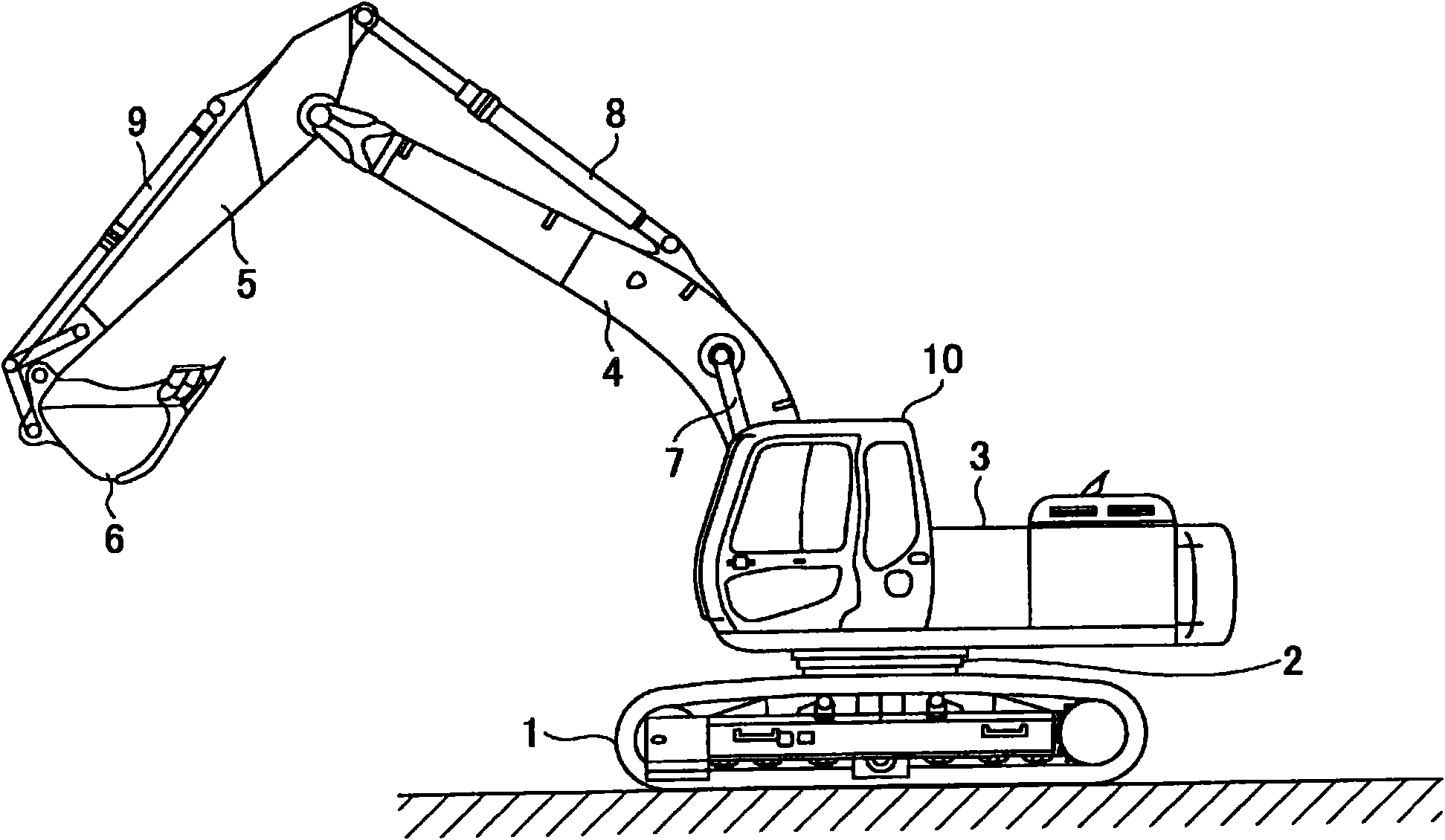
[0032] figure 1 It is a side view showing a construction machine including the turning drive control device according to the first embodiment.

[0033] A revolving upper body 3 is mounted on an undercarriage 1 of the construction machine via a revolving mechanism 2 . Furthermore, in addition to the boom 4, the arm 5, and the bucket 6, and the boom cylinder 7, the arm cylinder 8, and the bucket cylinder 9 for hydraulically driving them, the upper slewing body 3 is equipped with a cab 10 and a power supply. source.

[0034] "the whole frame"

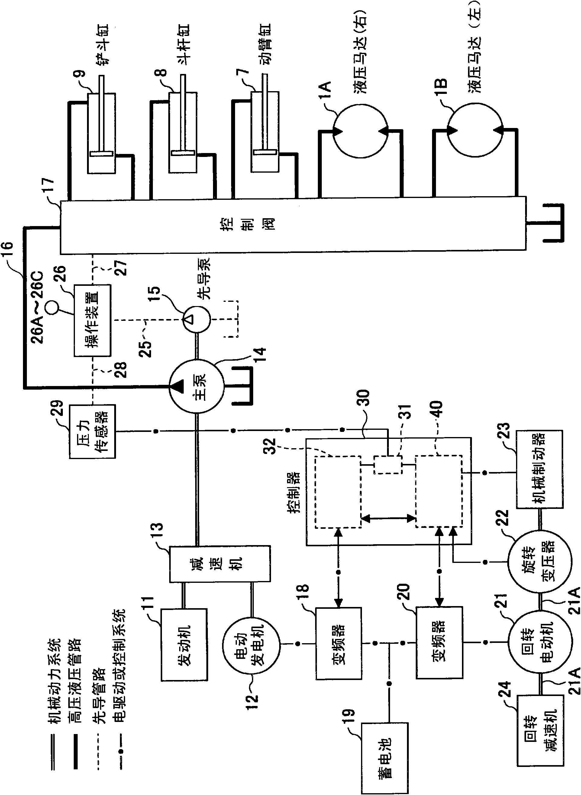
[0035] figure 2 It is a block diagram showing the configuration of a construction machine including the turning drive control device according to the first embodiment. in the figure 2 Among them, double lines, solid lines, dotted lines, and single-dot-dash lines represent mechanical power systems, high-pressure hydraulic lines, pilot lines, electric drive or control systems, respectively.

[0036] An engine 11 as a mechanical drive...

Embodiment approach 2

[0144] Figure 7 It is a control block diagram showing the configuration of the turning drive control device 40 according to the second embodiment. In Embodiment 1, a method was described in which the acceleration as the amount of time change of the rotational speed input from the turning motion detection unit 58 is calculated, and the direction of the acceleration is set as the torque direction (rotational rotation) of the turning shaft of the turning mechanism 2 . The torque direction on the rotating shaft 21a of the motor 21 is detected, and the rotation drive control is performed using the torque direction, but the difference between the rotation drive control device 40 of the second embodiment and the first embodiment is that based on The output torque current command value determines the direction of the torque and carries out the turning drive control. The other components are the same as those in Embodiment 1, so the same symbols are assigned to the same components an...

Embodiment approach 3

[0155] Figure 9 It is a control block diagram showing the configuration of the turning drive control device 40 according to the third embodiment. The turning drive control device 40 of Embodiment 3 is different from Embodiment 1 in that it includes an accelerometer 70 as a mechanism for detecting the turning direction, and the main control unit 60 detects the torque direction based on the acceleration detected by the accelerometer 70 (the turning motor 21 The torque direction on the rotating shaft 21a). The other components are the same as those in Embodiment 1, so the same symbols are assigned to the same components and their descriptions are omitted.

[0156] The main control unit 60 of the turning drive control device 40 according to Embodiment 3 detects the torque direction of the turning shaft of the turning mechanism 2 (the torque direction on the turning shaft 21a of the turning electric motor 21) based on the acceleration input from the accelerometer 70, and performs...


PUM


Abstract

The invention provides a swivel drive controller and a construction machine including the same. A swivel drive controller for controlling drive of a swivel mechanism on a construction machine which is swivel-driven by an electric motor includes a velocity command output section to output a velocity command for controlling rotation speed of the electric motor in accordance with the amount of operational input from an operational section on the construction machine, a torque direction detection section to detect a direction of the torque applied to a rotary shaft of the swivel mechanism, and a drive control section which generates a drive command for controlling the electric motor to control drive of the electric motor in accordance with the velocity command output from the velocity command output section. In case a swivel direction indicated by the velocity command output from the velocity command output section and a torque direction detected by the torque direction detection section are opposite to each other, the drive control section starts drive of the electric motor using the drive command in starting swivel of the swivel mechanism.

Description

technical field [0001] The present invention relates to a turning drive control device for driving control of a turning mechanism of a construction machine, and a construction machine including the turning drive control device. Background technique [0002] Conventionally, a construction machine including an electric motor as a power source of a turning mechanism for turning an upper turning body has been proposed. In such a construction machine, when the swing mechanism is accelerated (driven) by the electric power of the motor and decelerated (braked), the swing mechanism is regeneratively operated to charge the battery with generated electric power (for example, Patent Document 1). In addition, the construction machine described in this patent document 1 is provided with a hydraulic pump in order to hydraulically drive the driving mechanism other than the slewing mechanism, which connects the generator to the engine for driving the hydraulic pump through the speed increas...

Claims


Application Information

Patent Timeline
Patent Type & Authority Applications(China)
IPC IPC(8): E02F9/22B60K6/46B60K6/485B60W10/08B60W20/00B66C23/84E02F9/20H02P27/06
CPCE02F9/123E02F9/2075E02F9/2246H02P6/06
Inventor 佐野公则庄野博三
Owner SUMITOMO CONSTRUCTION MACHINERY
Why Eureka
Try Eureka