

Image capturing device, integrated circuit, image capturing method, program, and recording medium
A camera device and camera processing technology, which can be used in focusing devices, projection devices, televisions, etc., and can solve the problem of camera settings for shooting control settings, etc.
- Summary
- Abstract
- Description
- Claims
- Application Information
AI Technical Summary
Problems solved by technology
Method used
Image

Examples
Embodiment approach 1
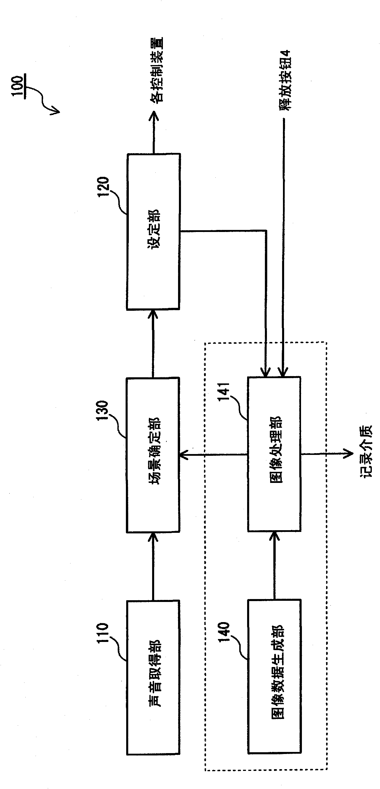
[0035] The digital camera 100 according to Embodiment 1 stores in advance a plurality of setting values for controlling the camera mechanism suitable for each shooting environment (hereinafter also referred to as "shooting scene"), and automatically determines whether to shoot based on surrounding sounds. The scene can be used to automatically set each setting value for the control of the camera mechanism suitable for the shooting scene, thereby reducing the user's operation burden and being used to generate beautiful images.
[0036]
[0037] First, the device configuration of the digital camera 100 according to Embodiment 1 will be described.
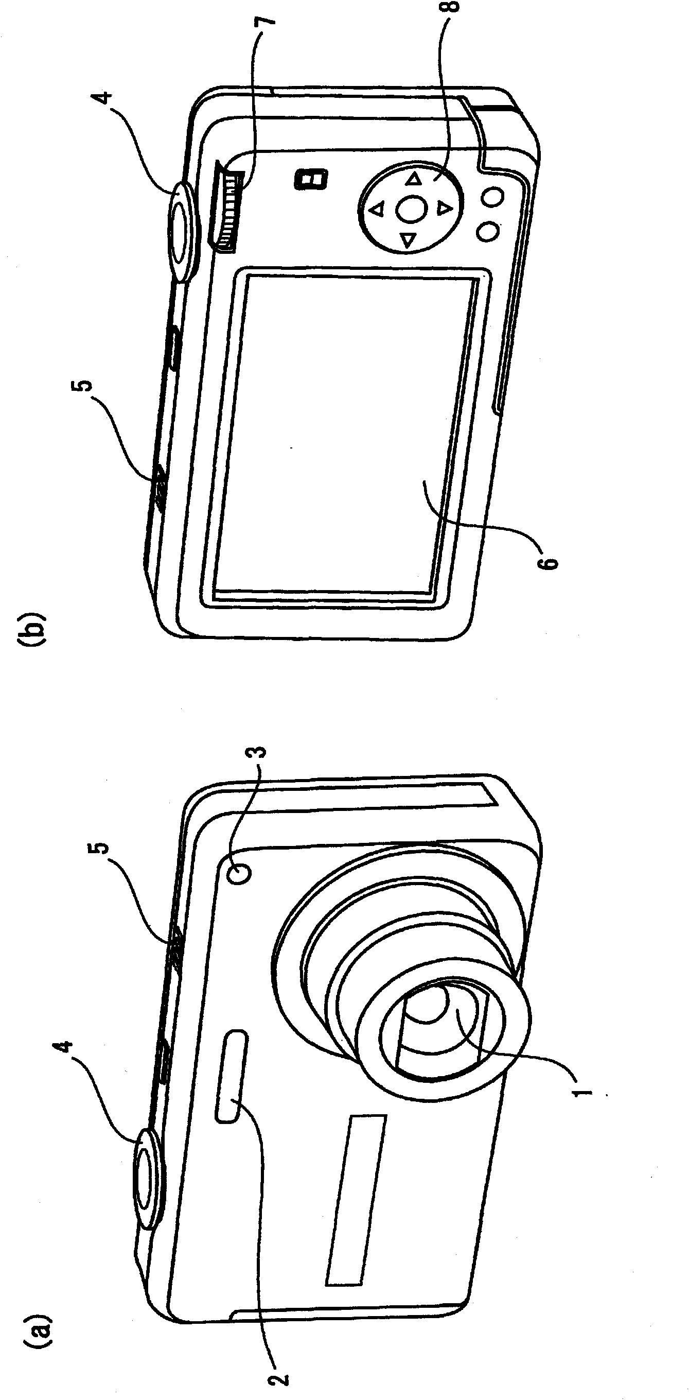
[0038] figure 1 (a) is a perspective view showing the appearance of the front and upper surfaces of the digital camera 100, figure 1 (b) is a perspective view showing the appearance of the rear and upper surfaces of the digital camera 100 .
[0039] Such as figure 1 As shown in (a), on the front of the digital camera 100, a pho...
Deformed example 1
[0158] In Embodiment 1, an example of automatically specifying one shooting scene and setting each setting value corresponding to the specified shooting scene is described, but the following describes presenting candidates of shooting scenes to the user and setting the settings corresponding to the selected shooting scene. A modified example of each setting value of the shooting scene selected by the user.
[0159] Thereby, the user can perform shooting at each setting value suitable for the shooting scene through simple operations. In addition, since the user makes the final decision on the shooting scene, it can be used to generate more beautiful images.
[0160] The digital camera according to Modification 1 (hereinafter referred to as "modified digital camera") is configured by slightly changing the function of the photographing scene determination unit 137 of the digital camera 100 according to the first embodiment, so the modified part from the digital camera 100 Descri...
Deformed example 2
[0179] In Embodiment 1, a method of judging a photographing scene based on surrounding sounds and automatically setting each setting value for photographing mechanism control suitable for the judged photographing scene was described. In addition to this, the camera mechanism control after the correction is automatically set when the detection target (human face, artificial object, etc.) is specified based on the surrounding sounds and the specified detection target can be detected from the image data. Variations of each setting value used.
[0180] In addition, the description below will focus on changes made to the digital camera 100 according to Embodiment 1 described above.
[0181]
[0182] First, the functional configuration of the digital camera 200 according to Modification 2 will be described.
[0183] Figure 14 It is a block diagram showing the functional configuration of main parts of the digital camera 200 .
[0184] As shown in the figure, digital camera 200 ...
PUM
 Abstract
Description
Claims
Application Information