
Air-driven rotary cutting tool

An air-driven, cutter technology, used in medical science, prosthodontics, dentistry, etc., can solve problems such as small head

Active Publication Date: 2011-05-11
MORITA MFG CO LTD
View PDF12 Cites 0 Cited by
  • Summary
  • Abstract
  • Description
  • Claims
  • Application Information

AI Technical Summary

Problems solved by technology

However, the rotation speed of the rotor obtained here is not enough to solve the above-mentioned problems, and it is necessary to reduce the rotation speed of the rotor more effectively while maintaining the torque.
In addition, in the case of the dental drill handpiece shown in this patent document, the rotor and the like are accommodated and supported through the air guide ring in the head, and the existence of the air guide ring is also one of the reasons why it is difficult to make the head smaller.

Method used


Image

  • Air-driven rotary cutting tool
  • Air-driven rotary cutting tool
  • Air-driven rotary cutting tool

Examples


Embodiment Construction

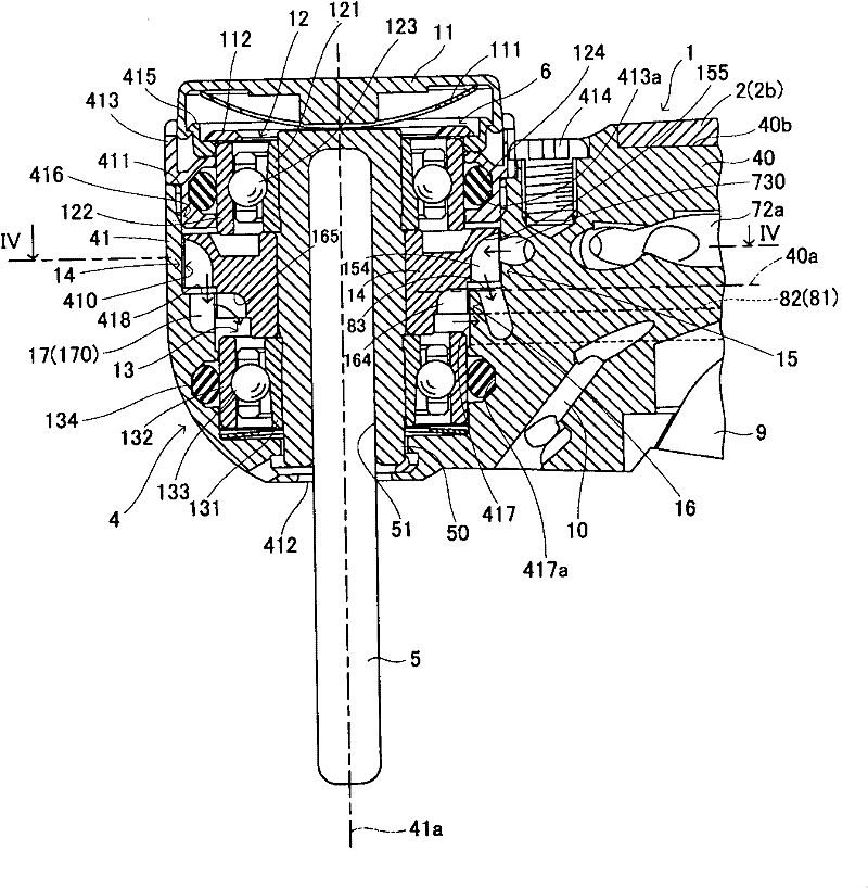
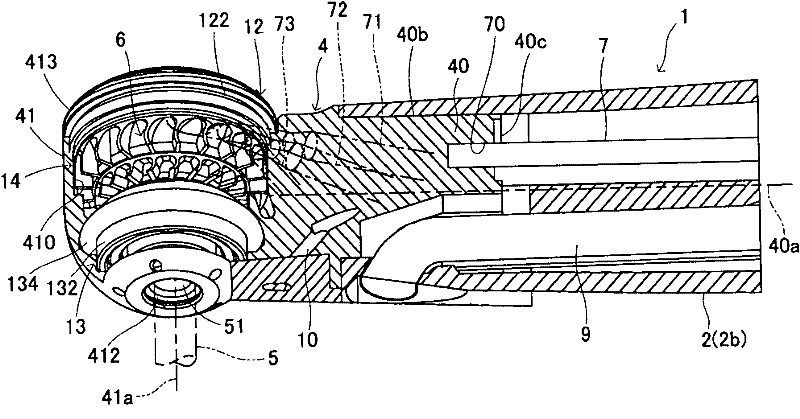
[0037] Hereinafter, an embodiment of the air-driven rotary cutter of the present invention will be described based on the drawings. figure 1 It is a side view showing the overall structure of a dental air-turbine dental drill handpiece as an embodiment of the air-driven rotary cutter of the present invention. in figure 1 Among them, the dental drill handpiece 1 has a handle portion 2 that is held by the operator during treatment. The base end of the handle portion 2 is provided with a medium for interacting with air, water, etc., like conventional dental drill handpieces. The connecting portion 2a to which the supply pipe 3 is connected has a head 4 connected to the front end of the handle portion 2 via a neck portion 2b. The cutting tool 5 is detachably attached to the head 4. Figure 2 ~ Figure 4 Is to figure 1 An enlarged view of the head 4 and its vicinity. As shown in these drawings, the head 4 integrally includes a shaft portion 40 connected to the front end of the handle...


PUM


Abstract

The invention relates to an air- driven rotary cutting tool which can reduce the rotating speed of rotor while keeping the torque of the rotor, and can miniaturize the head.The cutting tool is characterized by the first turbine vane having such a concave shape on its side seen in a direction into the rotary axis as to fall from upstream into downstream of its rotational direction of the rotor, and the second turbine vane having such a concave shape on its side as to fall into its opposite direction of the first turbine vane. According to the cutting tool of the present invention, the rotational speed of the rotor can be reduced without decreasing its rotary torque in addition to advantage in further downsizing of the head part.

Description

Technical field [0001] The present invention relates to an air-driven rotary cutter for medical, dental, or other cutting processing using pressurized air to rotate a cutting tool, and more specifically to a dental handpiece such as a gas turbine dental drill. Background technique [0002] Patent Documents 1 to 4 of the applicant disclose an air-driven rotary cutter that can be used for medical, dental, or other cutting processing. The air-driven rotary cutters disclosed in these patent documents each include a two-stage (Japanese: two-stage) rotor as a member that effectively converts the energy of pressurized air into rotational force. The two-stage rotor is composed of an annular hub, and a first turbine blade portion and a second turbine blade portion formed on the outer peripheral surface of the hub. Furthermore, the first turbine blade portion and the second turbine blade portion each include a plurality of first turbine blades and second turbine blades extending radially ...

Claims


Application Information

Patent Timeline
IPC IPC(8): A61C1/05
CPCA61C1/05A61C1/12
Inventor 高志哲也中山照三
Owner MORITA MFG CO LTD
Learn More