Steel rail flash welding machine and container type steel rail flash welding equipment

A flash welding machine, flash welding technology, applied in welding equipment, resistance welding equipment, metal processing equipment and other directions, can solve the problems of non-retractable boom, inability to adjust the boom, high noise of the pump station, etc., to achieve long service life, compact effect

Active Publication Date: 2011-05-11
METALS & CHEM RES INST CHINA ACAD OF RAILWAY SCI +1
View PDF8 Cites 11 Cited by
  • Summary
  • Abstract
  • Description
  • Claims
  • Application Information

AI Technical Summary

Problems solved by technology

In this kind of container-type flash welding equipment, the hydraulic pump station and the electric control cabinet are in the same compartment. Due to the high operating temperature of the hydraulic pump station, sometimes it is above 60 degrees, and the noise of the pump station is very loud, which is harmful

Method used


Image

  • Steel rail flash welding machine and container type steel rail flash welding equipment
  • Steel rail flash welding machine and container type steel rail flash welding equipment
  • Steel rail flash welding machine and container type steel rail flash welding equipment

Examples


Embodiment Construction

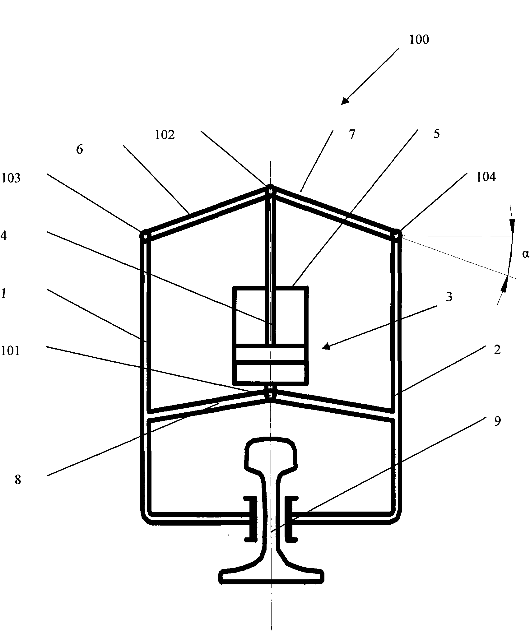
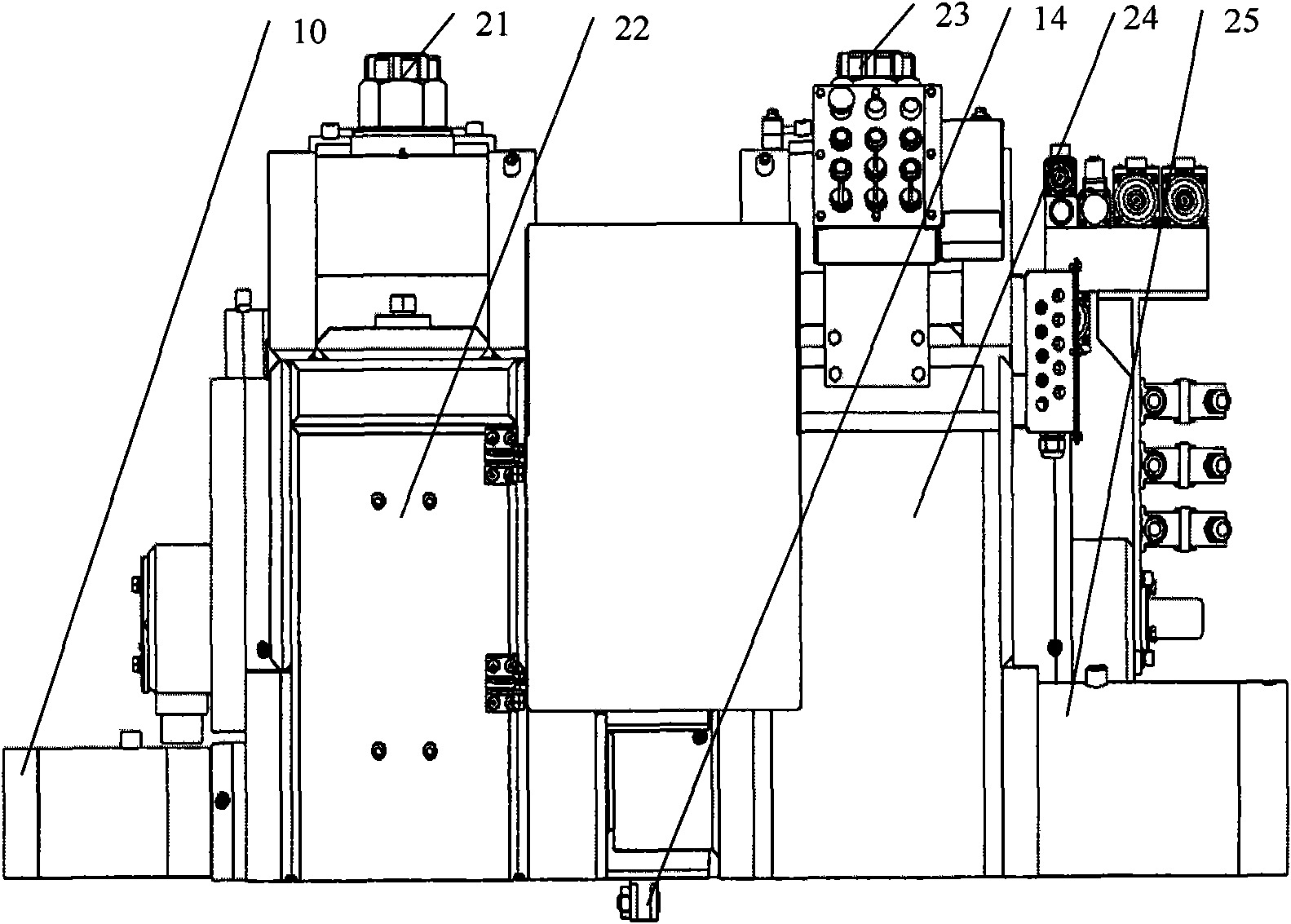
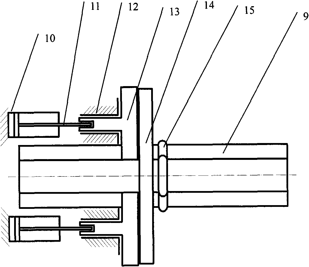
[0032] general reference figure 1 with 2 , shows a rail flash welder, which includes at least one fulcrum 101 mounted on the welder, at least two rail clamping mechanisms 100 mounted on the corresponding fulcrum, a flash welding transformer and at least At least one of the two rail clamping mechanisms makes the end of the clamped rail close to the upsetting actuation mechanism (here, the upsetting hydraulic cylinder 25). The at least two rail clamping mechanisms 100 may be mounted on a common fulcrum to facilitate alignment of the rails. Of course, these two rail clamping mechanisms can also be respectively installed on two different supporting shafts. The rail flash welder structure of the shown embodiment adopts a static rail clamping mechanism 24 and an axially movable movable rail clamping mechanism 22 . Alternatively, two moving rail clamping mechanisms that can approach each other can be used. Such as figure 2 As shown, before welding, the cylinders of the hydrauli...


PUM


Abstract

The invention provides a steel rail flash welding machine which comprises fulcrums arranged thereon, at least two steel rail clamping mechanisms arranged on the corresponding fulcrums, a flash welding transformer and an upset forging actuating mechanism. Each steel rail clamping mechanism comprises an operating mechanism, two lever structures and two connecting rod pieces, wherein the operating mechanism is provided with an operating rod capable of vertically applying force or actuating; the two lever structures can pivot around the fulcrums, and the lower end of each lever structure can loosen or clamp a steel rail; and one end of each connecting rod piece is pivotally connected with a common first pivot point on the operating rod, and the other end of the connecting rod piece is pivotally connected with one of second and third pivot points lower than the first pivot point on the corresponding lever structure, and the operating rod vertically applies the force to or actuates the connecting rod pieces, so that the lower ends of the lever structures loosen or clamp the steel rails. The invention also provides container type steel rail flash welding equipment with the steel rail flash welding machine.

Description

technical field [0001] The invention relates to the field of rail flash welding, in particular to a rail flash welding machine. In addition, the invention also relates to a container-type rail flash welding equipment with a rail flash welding machine. Background technique [0002] The seamless lines of railways are mostly welded by multi-section steel rails. Rail welding is generally classified as factory welding or on-site (on-line) welding. For field welding there are generally four types, namely flash welding, gas pressure welding, thermite welding and narrow gap arc welding. Among them, the quality of rails welded by mobile flash welding is the most stable, so it has become the main means of on-site rail welding. [0003] The basic principle of flash welding is to make the ends of the spliced ​​two rails short-circuit and generate heat, and then when they are heated to a certain temperature, the softened ends are quickly pulled together (upset) to complete the welding...

Claims


Application Information

Patent Timeline
IPC IPC(8): B23K11/04B23K11/36
Inventor 丁韦高振坤李力宋国强高文会李振华罗小三
Owner METALS & CHEM RES INST CHINA ACAD OF RAILWAY SCI
Why Eureka
Try Eureka