
Ground lifting machine for aerial remote sensor

A technology of aerial remote sensing and elevators, applied in the direction of lifting devices, etc., can solve the problems of lack of auxiliary equipment and other problems

Inactive Publication Date: 2011-05-11
CHANGCHUN INST OF OPTICS FINE MECHANICS & PHYSICS CHINESE ACAD OF SCI
View PDF7 Cites 5 Cited by
  • Summary
  • Abstract
  • Description
  • Claims
  • Application Information

AI Technical Summary

Problems solved by technology

Since aerial remote sensors are not universal equipment and lack necessary auxiliary equipment in the field, it is imperative to develop a ground lift for aerial remote sensors that can realize the above functions

Method used


Image

  • Ground lifting machine for aerial remote sensor
  • Ground lifting machine for aerial remote sensor
  • Ground lifting machine for aerial remote sensor

Examples


Embodiment Construction

[0015] The specific implementation manners of the present invention will be described in detail below in conjunction with the accompanying drawings.

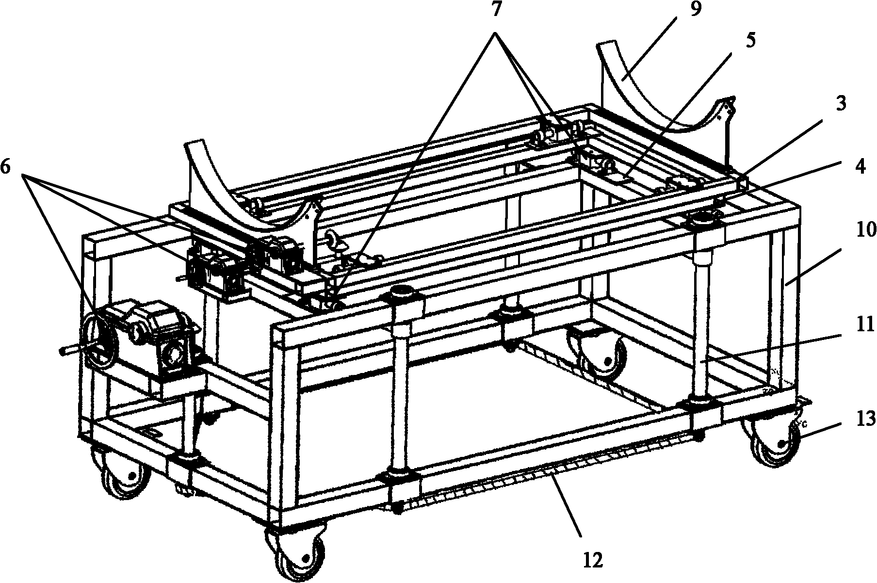
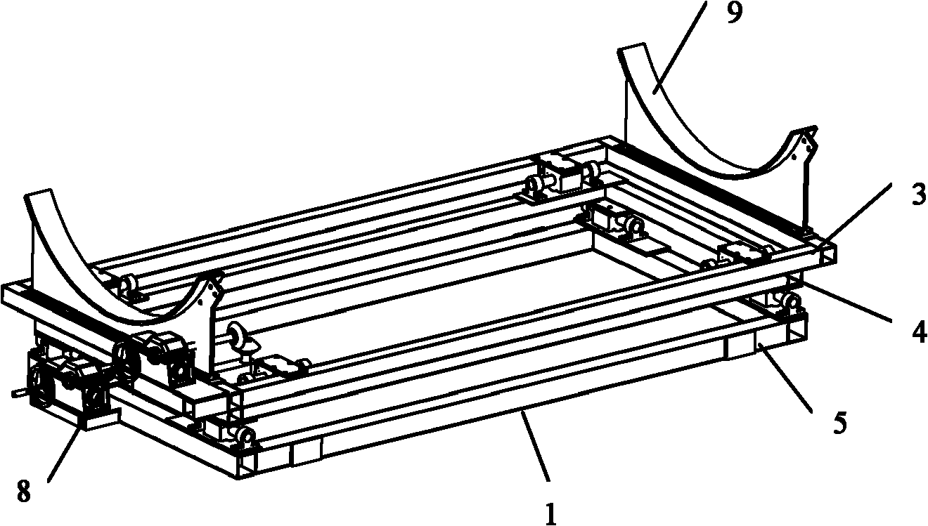
[0016] Depend on figure 1 Shown, a kind of ground elevator for aviation remote sensor of the present invention is characterized in that, comprises horizontal two-degree-of-freedom adjustment platform 1 and vertical adjustment platform 2, and said horizontal two-degree-of-freedom adjustment platform 1 is contained in the vertical adjustment platform 2.

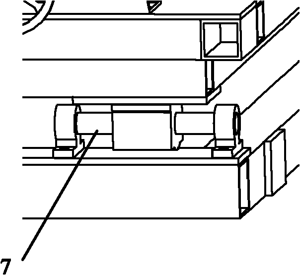
[0017] Depend on Figure 1-5 As shown, the horizontal two-degree-of-freedom adjustment table 1 includes an upper structure 3, a middle structure 4, a lower structure 5 and a worm gear reducer 6, between the upper structure 3 and the middle structure 4, and between the middle structure 4 and the lower structure 5 Both are connected by linear bearing pairs 7, and the worm gear reducer 6 is installed on one side of the lower structure 5, and is connected with the lower structure 5...


PUM


Abstract

The invention relates to the field of aerial machinery, in particular to a ground lifting machine for an aerial remote sensor. The ground lifting machine for the aerial remote sensor comprises a horizontal two-degree-of-freedom adjusting platform and a vertical adjusting platform, wherein the horizontal two-degree-of-freedom adjusting platform is arranged on the vertical adjusting platform. The ground lifting machine can be convenient to realize short-distance transportation of the aerial remote sensor, and can be rapid and reliable to realize accurate butt joint between an aerial remote sensor interface and an airplane interface in the direction X, the direction Y and the direction Z in the process of assembly and disassembly.

Description

technical field [0001] The invention relates to the field of aviation machinery, in particular to a ground lift for aviation remote sensors. Background technique [0002] During the use of the aerial remote sensor, it is necessary to safely, quickly and accurately realize the loading and unloading operation of the interface with the aircraft to ensure that the aerial remote sensor has a good working condition. Since the aerial remote sensor is not a universal device and lacks necessary auxiliary equipment in the field, it is imperative to develop a ground lift for the aerial remote sensor that can realize the above functions. Contents of the invention [0003] In view of the above situation, in order to solve the problems of the prior art, the purpose of the present invention is to provide a ground lift for the aerial remote sensor, which can adjust the aerial remote sensor in three directions. [0004] The technical solution adopted by the present invention to solve the ...

Claims


Application Information

Patent Timeline
IPC IPC(8): B66F11/04
Inventor 刘国嵩詹磊
Owner CHANGCHUN INST OF OPTICS FINE MECHANICS & PHYSICS CHINESE ACAD OF SCI
Learn More