Steel reinforcement cage for multi-ribbed composite wall and method for installing steel reinforcement cage

A reinforcement cage and composite wall technology, applied in the processing of walls and building materials, structural elements, etc., can solve the problems of excessive manpower and working hours, difficulty in improving the construction speed of manual binding of steel bars, and complicated binding procedures, etc., to ensure that Quality, faster binding or welding speed, easy quality effect

Inactive Publication Date: 2011-05-11
BEIJING JIAOTONG UNIV
View PDF5 Cites 8 Cited by
  • Summary
  • Abstract
  • Description
  • Claims
  • Application Information

AI Technical Summary

Problems solved by technology

[0006] (1) The binding process is very complicated, due to the large number of rib beams and rib columns, and the large number of beam-column nodes, and the reinforcement cage composed of longitudinal steel bars and closed stirrups must be formed by workers on-site binding
Therefore, it takes a lot of manpower and man-hours to bind the reinforcement cage at the construction site. The traditional arrangement of the reinfor...

Method used


Image

  • Steel reinforcement cage for multi-ribbed composite wall and method for installing steel reinforcement cage
  • Steel reinforcement cage for multi-ribbed composite wall and method for installing steel reinforcement cage
  • Steel reinforcement cage for multi-ribbed composite wall and method for installing steel reinforcement cage

Examples


Embodiment Construction

[0039] In order to make the above objectives, features and advantages of the present invention more obvious and understandable, the present invention will be further described in detail below in conjunction with the accompanying drawings and specific embodiments.

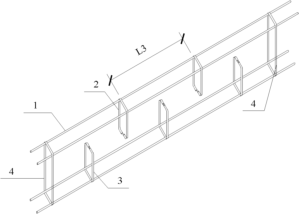
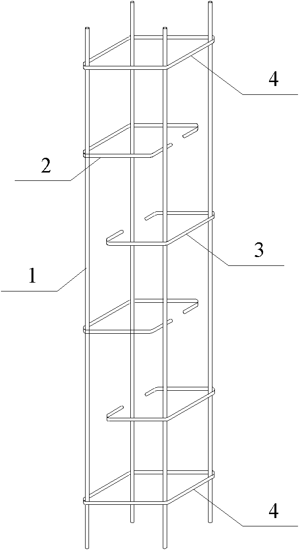
[0040] The steel cage of the present invention is arranged inside the rib beam or the rib column of the multi-ribbed composite wall. The length of the steel cage is equal to the length of the rib beam or column.

[0041] Reference figure 1 , Shows a three-dimensional structural diagram of Embodiment 1 of a steel cage for a multi-ribbed composite wall of the present invention. In this embodiment, the steel cage is arranged in the rib beam.

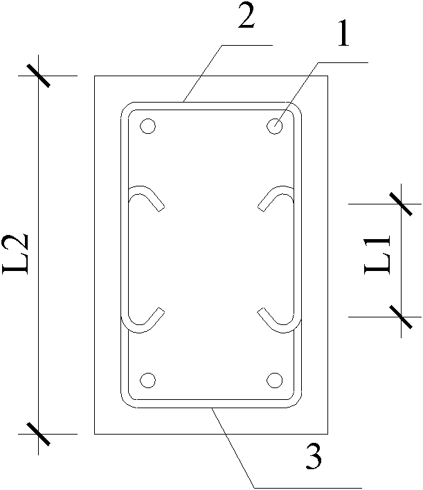
[0042] The steel cage includes: longitudinal steel bars 1, a first half-ring stirrup 2, a second half-ring stirrup 3, and a positioning closed stirrup 4; wherein the two sides and two bottom sides of the positioning closed stirrup 4 The first half-ring stirrup 2 is a groove shape with ...


PUM


Abstract

The invention provides a steel reinforcement cage for a multi-ribbed composite wall and a method for installing a steel reinforcement cage. The steel reinforcement cage comprises a longitudinal reinforcement, a first semicircular stirrup, a second semicircular stirrup and a positioning closed stirrup, wherein the first semicircular stirrup is in the shape of a groove the lower/right end of which is opened; the second semicircular stirrup is in the shape of a groove the upper/left end of which is opened; two side edges of the first semicircular stirrup and the second semicircular stirrup are respectively perpendicular to the bottom edges of the first semicircular stirrup and the second semicircular stirrup, and the ends of the two side edges are bent to the interiors of the grooves; the stirrup surfaces of the first semicircular stirrup, the second semicircular stirrup and the positioning closed stirrup are respectively mutually perpendicular to the trending direction of the longitudinal reinforcement; and the positioning closed stirrup is horizontally bundled around the whole longitudinal reinforcement, the first semicircular stirrup is horizontally bundled around the upper/left half part of the longitudinal reinforcement, and the second semicircular stirrup is horizontally bundled around the lower/right half part of the longitudinal reinforcement. The steel reinforcement cage and method provided by the invention have the advantages of reducing the workload for bundling reinforcements applied to reinforced concrete member or structure construction sites, and accelerating the construction speed.

Description

Technical field [0001] The invention relates to the technical field of building structures, in particular to a steel cage used in a multi-ribbed composite wall and a method for installing the steel cage. Background technique [0002] Reinforced concrete components or structures are composed of steel cages and concrete. The steel cages are composed of longitudinal steel bars and stirrups. After the steel cages are tied, concrete is poured to form a reinforced concrete component or structure. Traditional steel cages are formed by tying longitudinal steel bars and closed stirrups at the component or structure construction site by workers. That is, first locate the longitudinal steel bars in the component or structure, then locate the closed stirrups, and finally Close the stirrups and the longitudinal steel bars for binding to form a steel cage. [0003] With the development of building structure technology, new structural systems with multi-ribbed composite walls, grid seismic walls...

Claims


Application Information

Patent Timeline
IPC IPC(8): E04B2/84E04C5/01E04C5/02E04C5/06E04G21/12
Inventor 郭猛袁泉李鹏飞刘海涛
Owner BEIJING JIAOTONG UNIV
Why Eureka
Try Eureka