Steel reinforcement framework colligation bracket and steel reinforcement colligation construction method

A technology of steel skeleton and steel bar, applied in the field of construction auxiliary equipment, can solve the problems of inability to guarantee the size of steel skeleton, slow speed, etc., and achieve the effects of improving standardization, speeding up binding and simple structure

Inactive Publication Date: 2017-03-29
SHANDONG LUQIAO GROUP
View PDF8 Cites 3 Cited by
  • Summary
  • Abstract
  • Description
  • Claims
  • Application Information

AI Technical Summary

Problems solved by technology

Due to the huge number of steel bars that need to be bound, the traditional method of binding steel bars is not only slow, but also cannot guarantee the standard size of the steel skeleton during the binding process

Method used


Image

  • Steel reinforcement framework colligation bracket and steel reinforcement colligation construction method
  • Steel reinforcement framework colligation bracket and steel reinforcement colligation construction method
  • Steel reinforcement framework colligation bracket and steel reinforcement colligation construction method

Examples


Embodiment Construction

[0024] In order to make the object, technical solution and advantages of the present invention clearer, the present invention will be further described in detail below with reference to the accompanying drawings and examples.

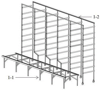
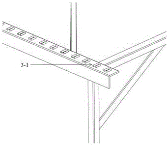
[0025] refer to figure 1 , a steel bar frame binding bracket, including a horizontal steel bar fixing structure 1-1 and a longitudinal steel bar fixing structure 1-2, refer to figure 2 and image 3 The transverse steel bar fixing structure 1-1 includes a steel bar skeleton support and a plurality of bayonets 3-1 for fixing the transverse steel bars arranged above the steel bar skeleton support 1-1, refer to Figure 4 The longitudinal reinforcement fixing structure 1-2 includes a support frame and a plurality of pipe bodies 4-1 on the support frame for inserting steel bars.

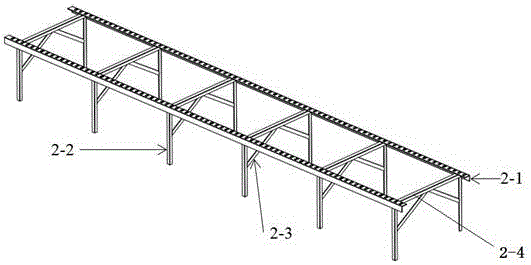
[0026] refer to figure 2 , the steel frame support includes two vertical bodies 2-1, multiple horizontal bodies 2-4 and multiple support bodies, the two vertical bodies 2-1 are...


PUM

PropertyMeasurementUnit
lengthaaaaaaaaaa
diameteraaaaaaaaaa

Abstract

The invention provides a steel reinforcement framework colligation bracket and a steel reinforcement colligation construction method. With adoption of the steel reinforcement colligation construction method, steel reinforcement framework colligation can be conveniently, rapidly and accurately carried out. The steel reinforcement framework colligation bracket comprises a transverse steel reinforcement fixing structure and a longitudinal steel reinforcement fixing structure; the transverse steel reinforcement fixing structure comprises a steel reinforcement framework support and a plurality of bayonets arranged above the steel reinforcement framework support and used for fixing transverse steel reinforcement; the longitudinal steel reinforcement fixing structure comprises a support frame and a plurality of pipe bodies; and the pipe bodies are arranged on the support frame and used for inserting in steel reinforcement. The steel reinforcement colligation construction method comprises the following steps: according to the design specifications, splicing the steel reinforcement framework colligation bracket to a reasonable length, and adopting a gradienter to adjust the steel reinforcement framework colligation bracket to be horizontal; putting transverse steel reinforcement in the bayonets; inserting the steel reinforcement with reasonable length in the pipe bodies of the support frame, and starting to arrange longitudinal steel reinforcement; and after colligation of the steel reinforcement frameworks, hoisting the steel reinforcement frameworks to a concrete pouring die.

Description

technical field [0001] The invention belongs to the field of construction auxiliary equipment. The invention relates to a steel bar frame binding bracket and a steel bar binding construction method, which are suitable for conveniently and quickly binding the steel bar frame in the bridge construction process. Background technique [0002] In the process of expressway construction, cement reinforcement is an important method to ensure the strength of concrete structures. In bridge structures such as cover beams and beams, due to the need to bear large loads, in order to ensure the strength of reinforced concrete structures, it is necessary to arrange a large number of load-bearing structures. steel bars. The layout of the reinforcement is not random, but needs to be calculated and analyzed to obtain the most efficient and reasonable distribution of reinforcement by looking up the specifications. Due to the huge number of steel bars that need to be bound, the traditional meth...

Claims


Application Information

Patent Timeline
Patent Type & Authority Applications(China)
IPC IPC(8): E01D21/00E04G21/12
CPCE01D21/00E04G21/12
Inventor 韩延吉孙德林刘铭张金昌许恩宾陈允禄
Owner SHANDONG LUQIAO GROUP
Why Eureka
Try Eureka